AISC
The Eskenazi School of Art, Architecture + Design
Merit Award - Less than $15 million
In 1952, Ludwig Mies van der Rohe designed a house for the Pi Lambda Phi fraternity on the main campus of Indiana University in Bloomington, but funding cuts relegated the plans to the MoMA archives. Exactly 70 years later, students now get to enjoy that space--not as a fraternity house, but as a design school.
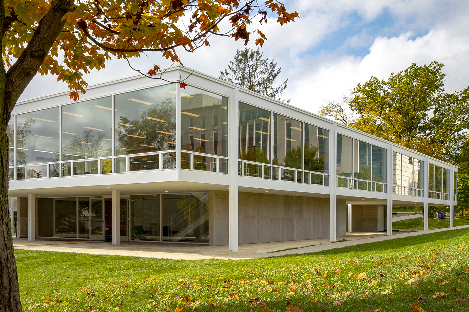
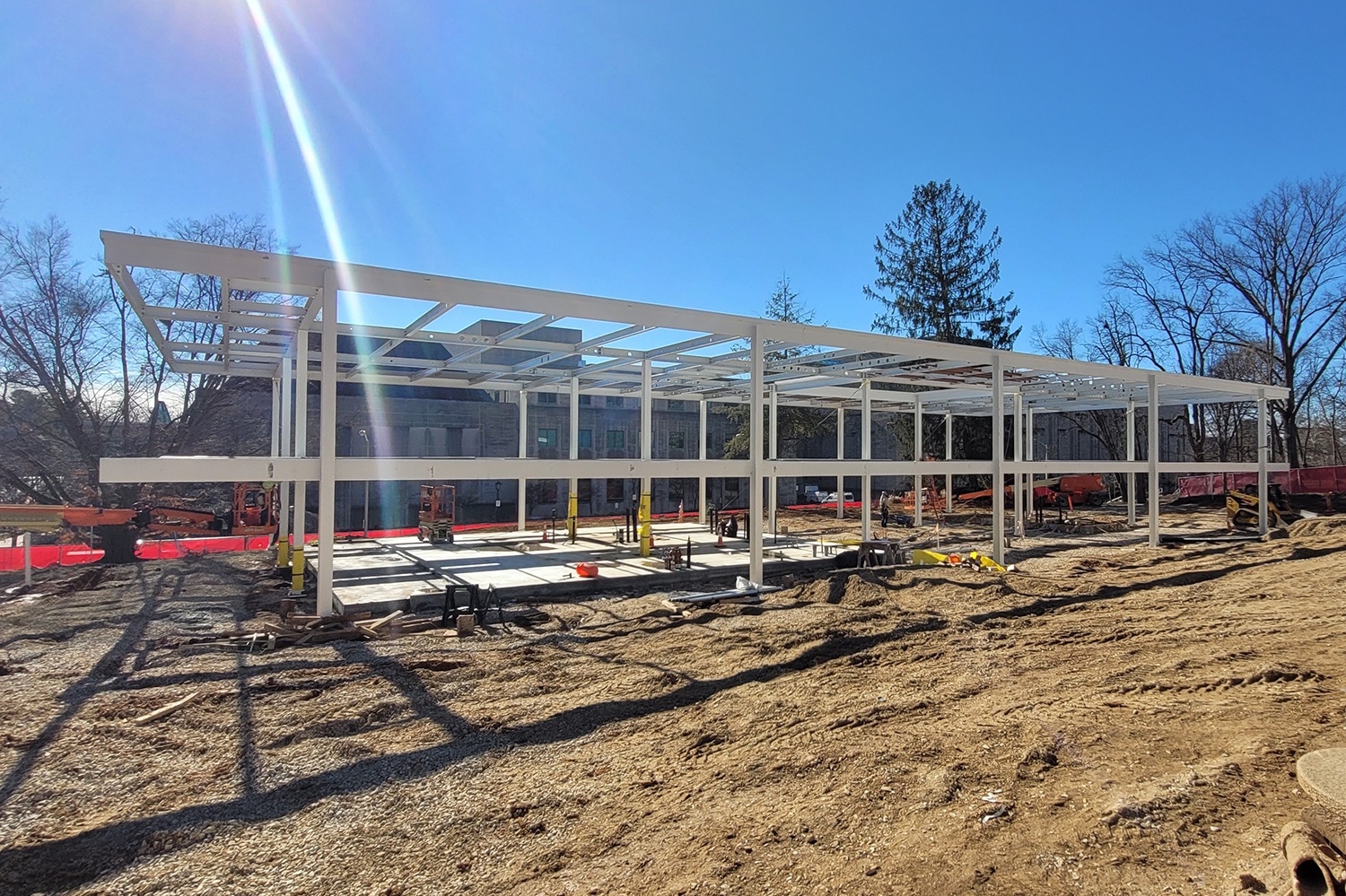
The newly completed Eskenazi School of Art, Architecture + Design is a modern revival of van der Rohe’s design. The new/ old building was brought back to life through a recent collaboration between architect Thomas Phifer and Partners and structural engineering firm Skidmore, Owings and Merrill (SOM). The team studied the original plans, drawings, construction details, and calculations while comparing them to similar van der Rohe buildings of the time. The team also gathered all available notes from the famed “less is more architect,” including the original structural calculations for a similar building by Myron Goldsmith, formerly of SOM and van der Rohe’s offices. A key challenge was to stay true to the original design intent while simultaneously aligning the project with current building codes and environmental considerations.
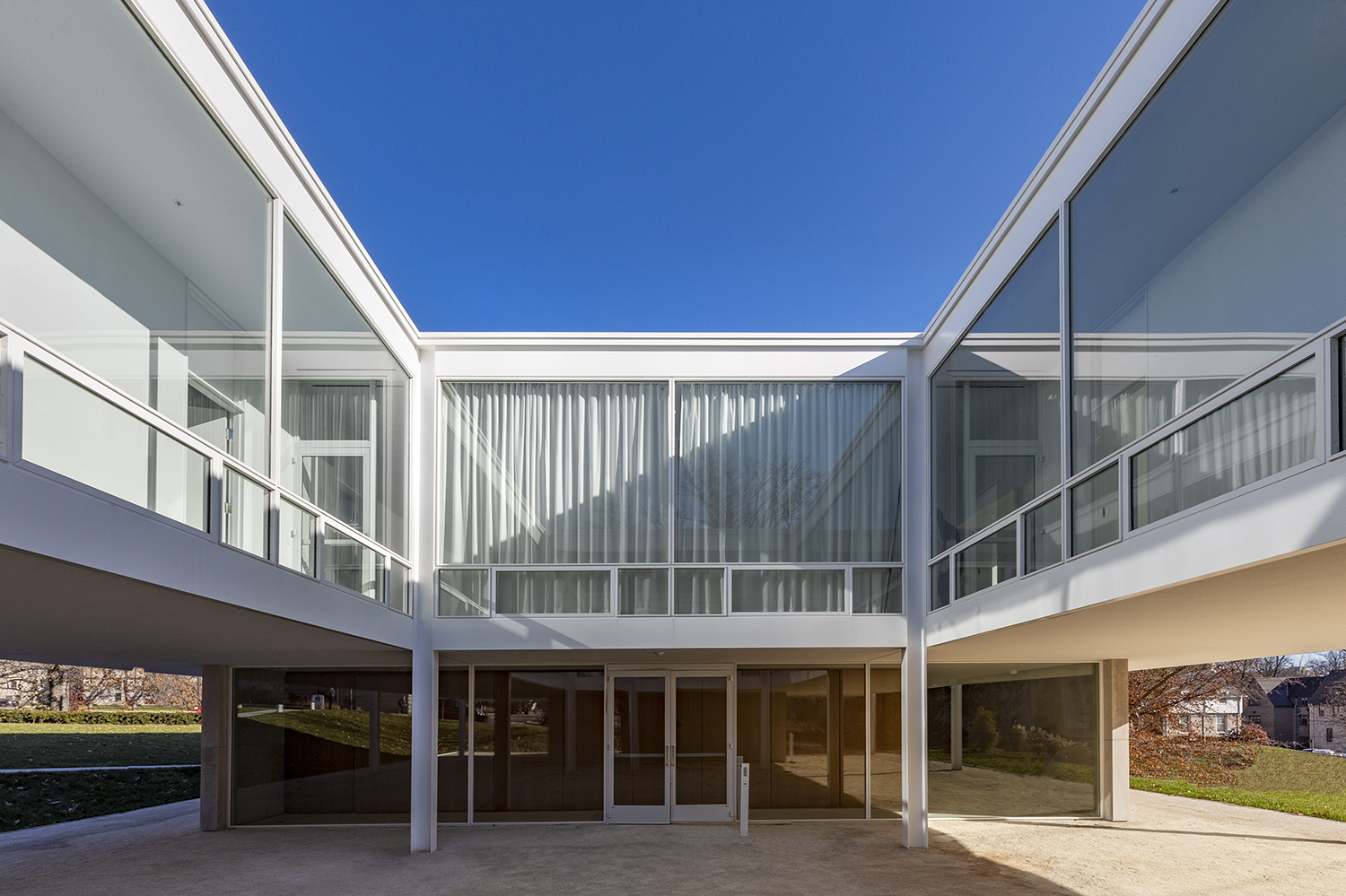
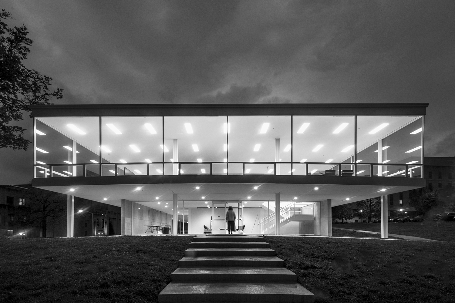
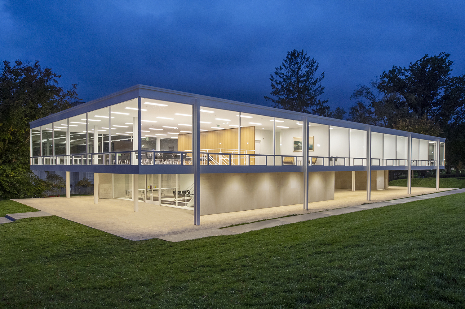
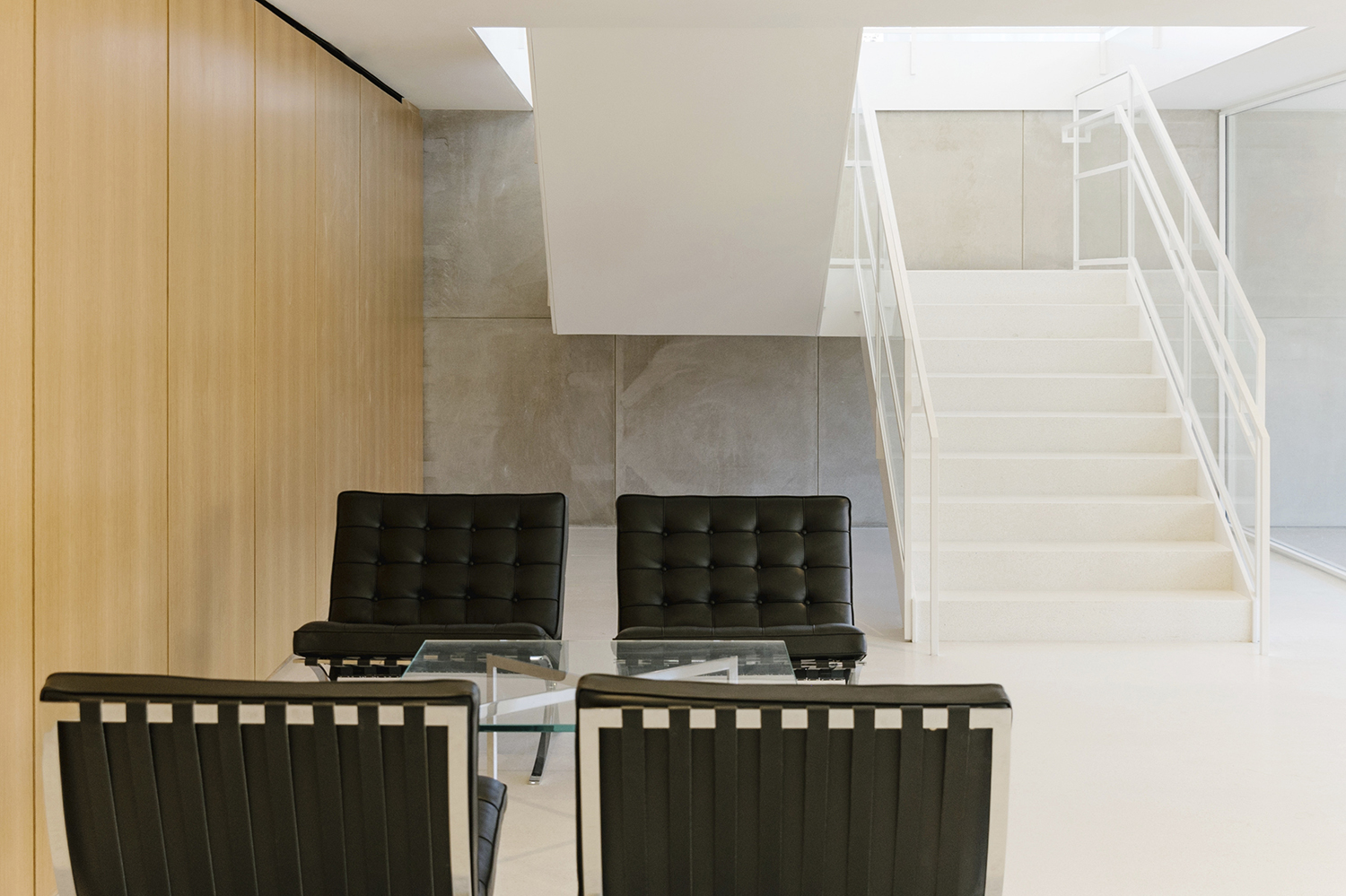
The two-story, nearly 10,000-sq.-ft building, which officially opened in April 2022, features a lecture hall, offices, and meeting rooms for faculty and staff. The ground floor is mostly open, while a central square atrium carves the upper level. The design brings abundant light to the interiors with a white-painted steel frame and floor-to-ceiling windows. The original design was followed with only minimal alterations to the visible architecture. Changes to the ground level included the reconfiguration of the stairs to comply with current safety codes, in addition to an expanded mechanical room, and other modifications included the addition of a hydraulic elevator and changing the glazing from a single pane to high-performance insulating glass. The second floor of the original design remained largely intact, repurposed from bedrooms to offices.
Since the structure was a recreation of an original design in steel, steel was the only viable option. Then as now, it provided a crisp aesthetic to the defined edges of the columns and mullions and also allowed for a thinner floor slab, providing more space for the MEP services in the 15-in. ceiling sandwich.
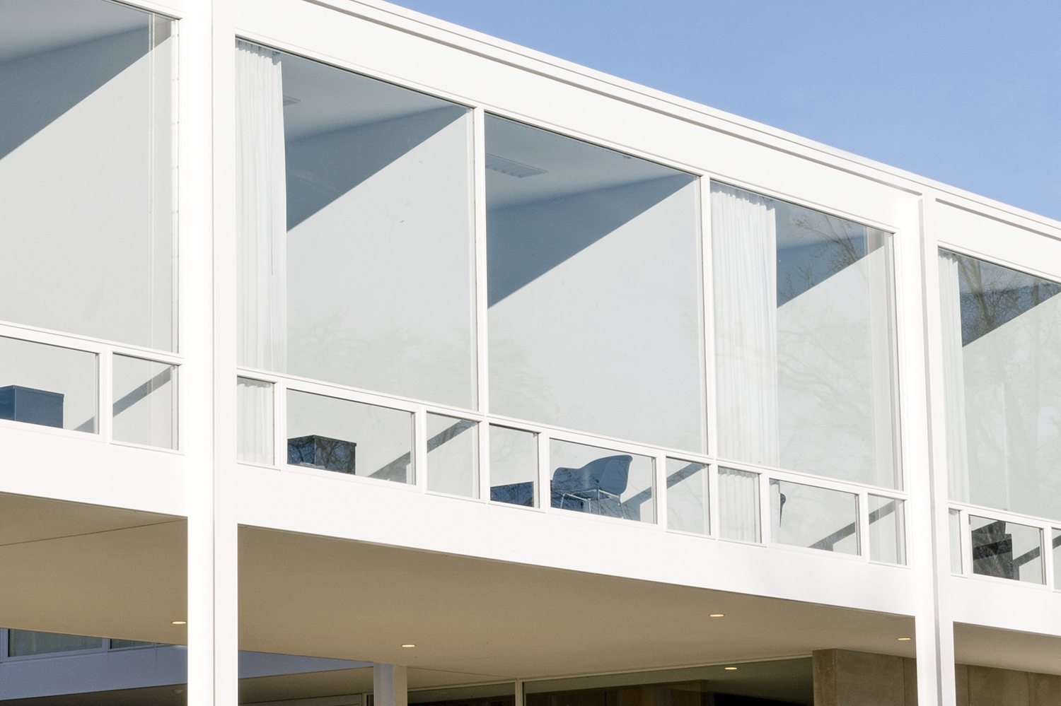
The primary structural challenges included engineering the steel mullions to accommodate insulating glass, wind loads, and building movements with minimal changes to the mullion profile of a typical van der Rohe design; coordinating MEP services through the 10-in. beams--in particular, locating and engineering the relatively large openings in the beams for air-conditioning ductwork, which the original design did not have; and creating structural details with no visible welds or bolts while simultaneously having all site connections bolted to facilitate erection provided some adjustability to maintain the very tight tolerances.
The solution for the mullion challenge was to use steel bars for the structural core of the mullions with glazing stops screwed to the steel bar core. The steel bar had the center machined to a 3⁄8- in. web to create a 1-in. glazing pocket, which was the dimension required to accommodate tolerances and frame wind load racking and vertical floor deflections. For mullion deflection calculations, the glazing stops were included in the mullion stiffness properties. The machining and careful selection of mullion stop screw size and spacing resulted in the absolute minimum mullion size.
There was a total of 15 in. available for the slab, steel framing, insulation, services, and ceiling for the MEP services, a depth that was dictated by the perimeter spandrel channel size, which was the same as the original design. The team specified a 2-in. slab over one ½-in. metal deck to achieve this extremely thin sandwich. The slab also had embedded radiant heat pipes, which required careful engineering and coordination of the slab system. For the building services, the second-floor beams had 220 openings in the steel girders varying in size from 3-in. round to 20-in. by 6-in. rectangular, with the latter openings requiring in-depth calculations to validate their strength.
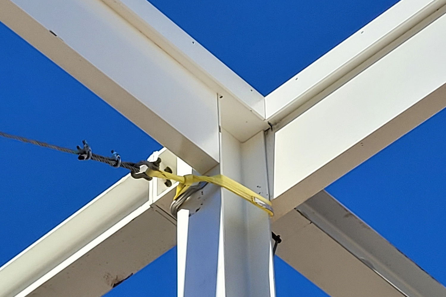
All beams and girders on column lines were designed considering the connections as partially restrained for lateral load resistance and minimized deflections. Flush bolted end plates were used at the beam-to-column connections, and the built-up girders ran over the columns with end plate splices near the cantilever back-span inflection point. The channel spandrels also had bolted end plate connections near the inflection points (two on each façade) with corners shop welded. The end plate connections were subsequently seal welded and ground flush to provide the appearance of a continuous member. Beam-to-perimeter columns were bolted to studs welded to columns to eliminate the requirement for any welding on the exterior with the connection configured so the channel could be erected and bolted first, followed by the end plate connected beam.
In addition to resisting wind loads on the glazing system, the vertical steel mullions also provide part of the second-floor gravity system. This is required since the second-floor channel spandrel at 15 in. was not adequate to span 30 ft, nor was it adequate for deflections of the 10-ft cantilevers. The vertical steel mullions are, therefore, rigidly bolted between the roof and second-floor spandrels, allowing part of the second-floor load to be shared by the roof spandrels, which have less load than floor spandrels. Also, rigidly connecting the spandrels together eliminates differential vertical deflection between the roof and floor, allowing a smaller glazing pocket than required.
The individual mullion elements are bolted to the structural frame with countersunk bolts in the glazing pockets. Horizontal mullions are attached to the vertical mullions with screws. The end plate connection of the vertical mullions is contained within the glazing pocket, so it is not visible from the exterior. By containing all fasteners within the glazing pocket, no fasteners were visible, and no welds were required, which allowed for crisp corners and edges for all the mullion elements without the need for grinding welds. Although integrating mullions in the structural system is not necessarily a new idea (as a matter of fact, the original design used this concept), connecting the glazing system with only screws and bolts, with the only visible fasteners being those attaching the glazing stops, was developed in a very innovative way.
Judge comment: “It’s amazing to see that the team was able to honor the original design that Mies had. You can’t separate the idea of steel and the idea of that building--steel is the only thing that could make that building work. When it’s executed at that level, with that sensibility for detail and attention to the original intent of the architect, it’s a magical experience to see a building come together like that.” -Anders Lasater, AIA, architect and principal, Anders Lasater Architects
Owner: Indiana University, Bloomington, Ind.
General contractor: CDI Inc., Terre Haute, Ind.
Architect: Thomas Phifer and Partners, New York
Structural engineer: Skidmore, Owings & Merrill (SOM), Chicago
Steel fabricator and detailer: MAK Steel Services, LLC, Seymour, Ind. *AISC full member*
- Project Category: Year 2023
- Location: Bloomington, IN
- Submitting Firm: SOM
- Photo Credit: 1, 2, 3, 4 - Hadley Fruits; 5, 6 - SOM; 7, 8 - Anna Powell Denton