National Steel Bridge Alliance
Portageville Bridge Replacement
Merit Award -- Major Span
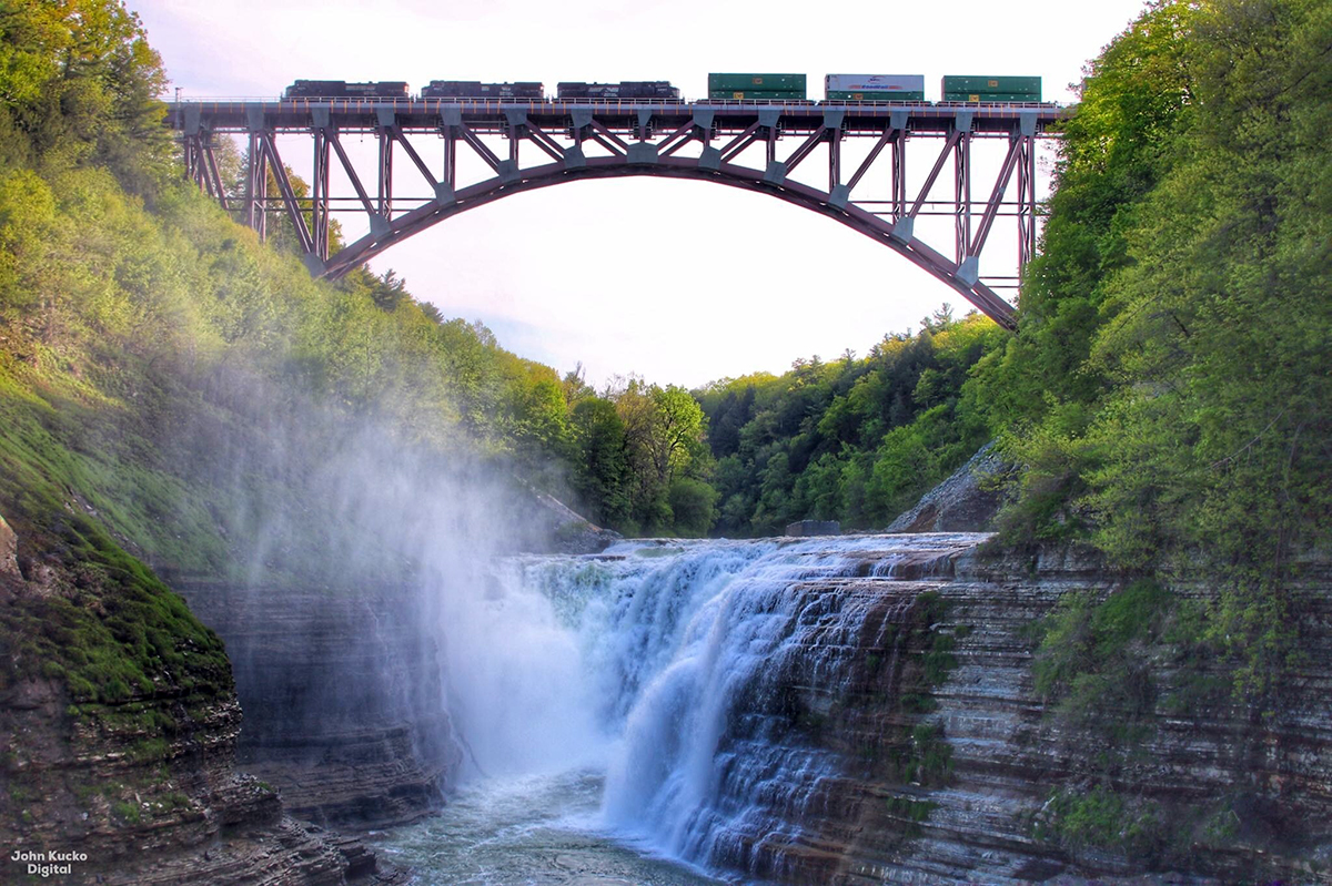
The new Portageville Bridge had big shoes to fill, so to speak.
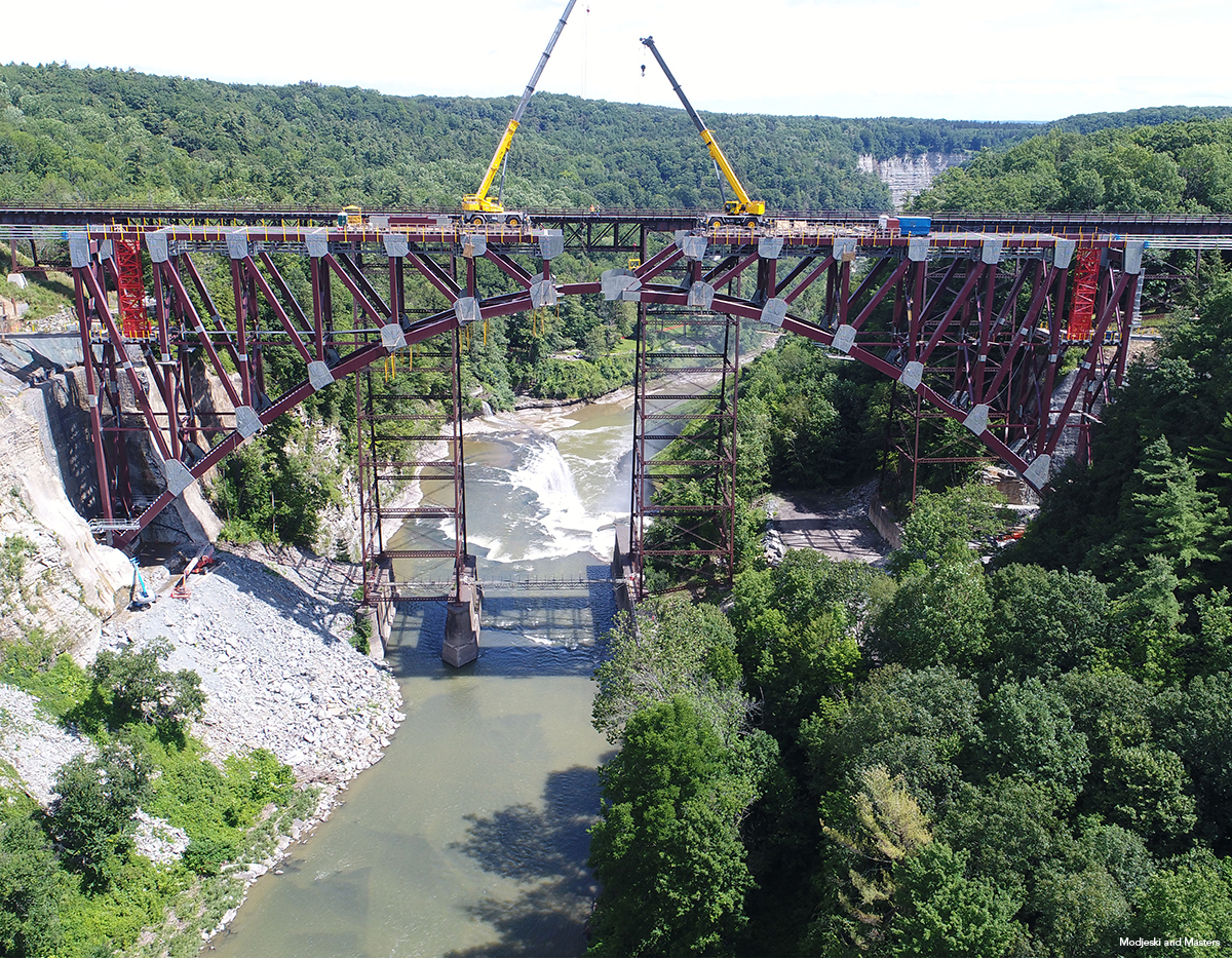
The original bridge crossed the scenic Genesee River Gorge, known as the “Grand Canyon of the East,” in Letchworth State Park in Portageville, N.Y., which hosts more than a million visitors a year thanks to its stunning scenery, including three large waterfalls. The new bridge, adjacent to where its predecessor once stood, is located directly above the Upper Falls.
Built in 1875, the old viaduct bridge was considered iconic within the Park and it was expected that a new bridge would need to be as well. After nearly a decade of public meetings, stakeholder input, environmental study, and engineering analysis, the team determined that the new bridge would be a spandrel-braced arch. Nine different options went through an evaluation process defined by New York’s State Environmental Quality Review Act, which considered the project objectives and the site’s unique characteristics. Ultimately, the team concluded that removing the existing bridge and building a new bridge on a parallel alignment would be the best option.
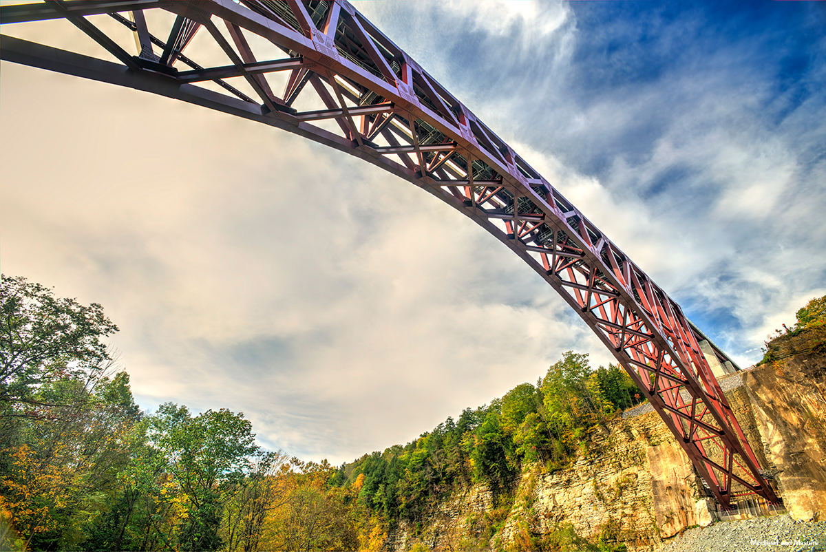
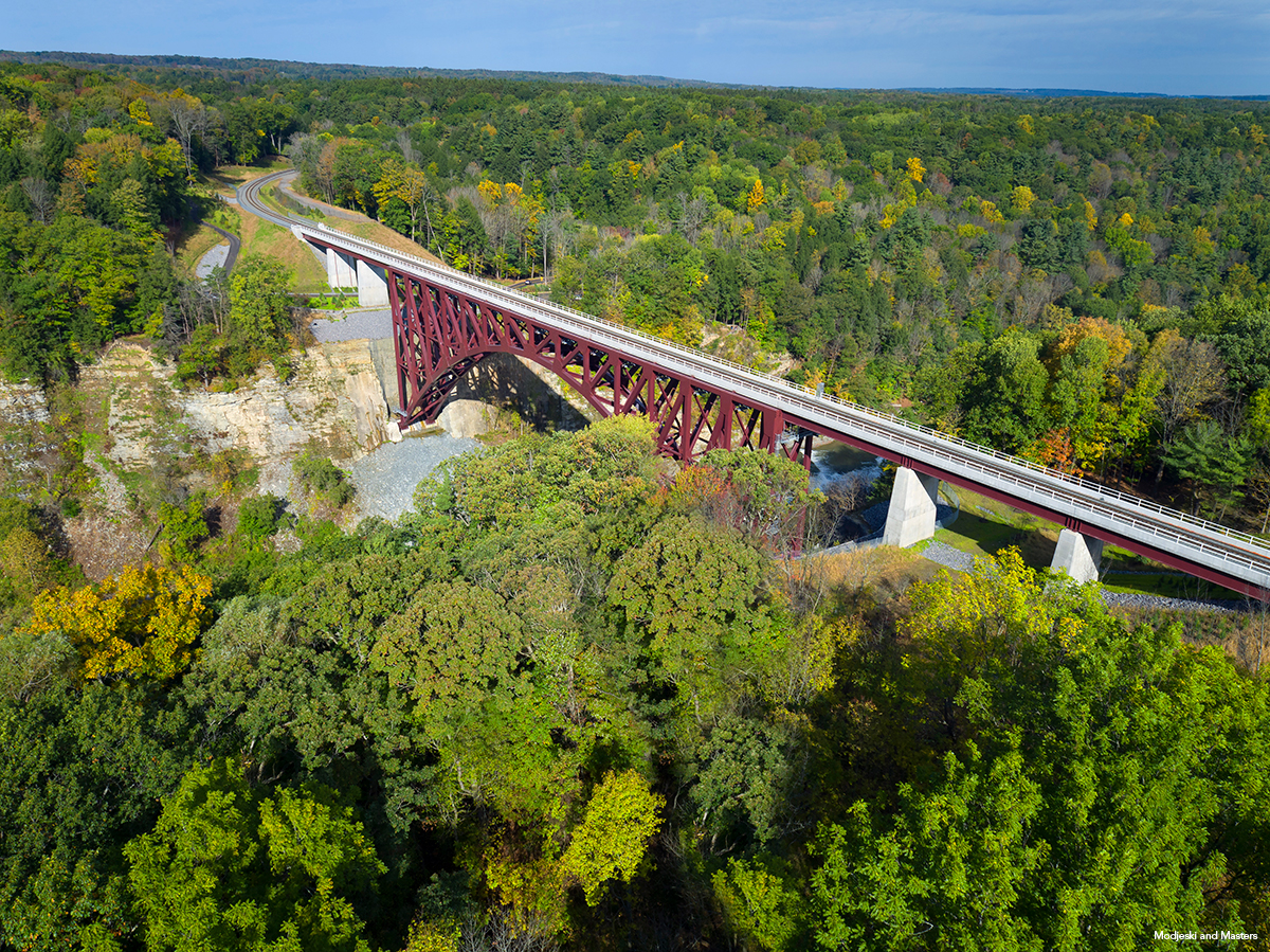
The selected design is the first true arch bridge built for the rail industry since the late 1940s. Modjeski and Masters (M&M) led the structural design of the new 483-ft-long arch. The arch is flanked on both sides by three 80-ft-long welded girder spans, and the track is supported across the bridge with a 20-ft-wide concrete ballast deck. The welded girder spans are supported on reinforced concrete piers and abutments that are founded on micropiles.
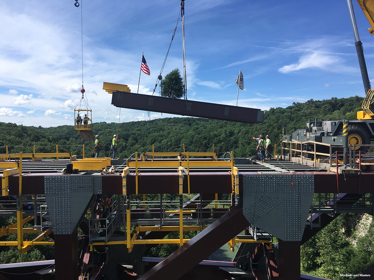
The bridge’s span exceeded the guidance provided by the American Railway Engineering and Maintenance-of-Way Association (AREMA) Manual for Railway Engineering, which is primarily used on simple-span bridges less than 400 ft in length, and thus required project-specific design criteria. The arch was erected in two halves, from the east and west skewback foundations, using the cantilever method. An “arch tieback system” was designed to support each arch half during cantilever erection up until arch closure. Each tieback system tied into the gusset plate at the end of top chord of the arch, and then anchored into a guy tower and backstay system with 12 cables. The guy towers transferred cable demands to a series of back stay members and directed the vertical components into the permanent approach span abutment. The backstays were connected to a grillage system anchored by 140-ft-long pretensioned rock anchors.
Each individual cable was connected to a tensioning device equipped with a jacking rod and center-hole jack, which was used to adjust the cable lengths and thus the arch geometry during erection and arch closure. The deflection of the arch and the tension in the tieback system cables were monitored throughout cantilever erection stages. Field-recorded values were compared to theoretical values obtained from a staged construction analytical model to ensure the arch closure geometry was eventually achieved. At the arch closure stage, the geometry for each half was fine-tuned using the tieback system until the bolt holes in the lower center panel point were aligned.
The gorge walls had an irregular shape and were not easily accessible. The difficult terrain would have made conventional surveying methods difficult, so the team used lidar scanning to make a preconstruction survey of the gorge walls. This preconstruction survey was used for placement of cranes and the determination of lifting radius. An additional lidar scan verified excavated quantities after the gorge pockets were completed.
The AREMA guideline for spacing trusses at 1/15 of span length was not followed, due to the unnecessary width that would be added due to the long span. The structure was proportioned such that no load combination produced uplift, except for a few combinations during construction staging. Plate thicknesses of box members were sized to preclude the need for longitudinal stiffeners. The main members were designed including in-plane and out-of-plane bending moments. As many of the applied loads can be multi-directional and thus cause moments to change direction, a conservative assumption was made to combine them in an additive manner and match the polarity of the axial loading under investigation.
A memorandum of agreement between the Federal Highway Administration; Norfolk Southern; New York State Department of Transportation; the New York State Office of Parks, Recreation, and Historic Preservation; the National Park Service; and various Indian Nations was created to produce a mutually agreed plan to avoid, minimize, or mitigate the impacts on various historic and cultural resources. The agreement stipulated that portions of the existing bridge would be salvaged and displayed to mitigate the removal of the bridge. A construction protection plan avoided impacts on other historical resources, and additional plans protected endangered species, such as northern long-eared bats, timber rattlesnakes, and bald eagles.
Project Team
-
Steel fabricators:
-
Canam-Bridges, Point of Rocks, Md. (arch bridge) *AISC MEMBER*
-
Veritas Steel, LLC, Lisle, Ill. (approach deck girder steel spans) *AISC MEMBER*
-
-
Steel detailer: DBM Vircon Services, Port Conquitlam, B.C., Canada *AISC MEMBER*
-
Steel erector and general contractor: American Bridge Company, Coraopolis, Pa. *AISC MEMBER* *AISC CERTIFIED*
-
Engineer: Modjeski and Masters, Mechanicsburg, Pa.
-
Owner: Norfolk Southern Corporation, Atlanta
Prize Bridge Information
- Year Awarded: 2020
- Year Completed: 2017
- Location: Portageville, NY
- Award Class: Major Span
Structure Information
- Span Length (ft): 483
- Structure Length (ft): 963
- Average Deck Width (ft): 22
- Steel Weight/Deck Area (lb/ft²): 0.2
- Amount of Steel (tons): 4300