Steel Solutions Center
3.5. Other General Information
3.5.1. How are tolerances determined if they are not addressed in the applicable standards?
The fabrication and erection tolerances in the AISC Specification, the AISC Code of Standard Practice, AWS D1.1/D.1.1M, and other applicable specifications and codes have evolved for nearly a century. Although these standards generally present a workable format for the fabricator and erector, they tend to address individual members rather than the role of individual members in the completed structure.
Tolerances for assemblies—such as those on shop-assembled bents, frames, platforms, pairs of girders, etc.—are not covered by any code or standard. AWS D1.1/D1.1M Clause 7.22.12 states that “other dimensional tolerances of members not covered by [Clause] 7.22 shall be individually determined and mutually agreed upon by the contractor and the owner with proper regard for erection requirements.” This practice is recommended in all cases. The agreed-upon tolerances should account for the erection tolerances specified in the AISC Code of Standard Practice.
3.5.2. Can more restrictive tolerances than those shown in the AISC Code of Standard Practice be met for the overall structural steel frame?
More restrictive tolerances could possibly be met, but this might involve a higher cost. Special clearances or tolerances may be difficult or impossible to achieve because of considerations such as temperature change, fabrication and construction procedures and erection stresses. When specified, such requirements must be identified in the contract documents. The additional cost of special or more restrictive tolerance requirements should be justified.
3.5.3. How can the accumulation of mill, fabrication, and erection tolerances be economically addressed?
While individual member tolerances are usually self-compensating and of minor significance in the overall structure, the possibility exists that these tolerances may accumulate and lead to unacceptable misalignments that are difficult to correct in the field.
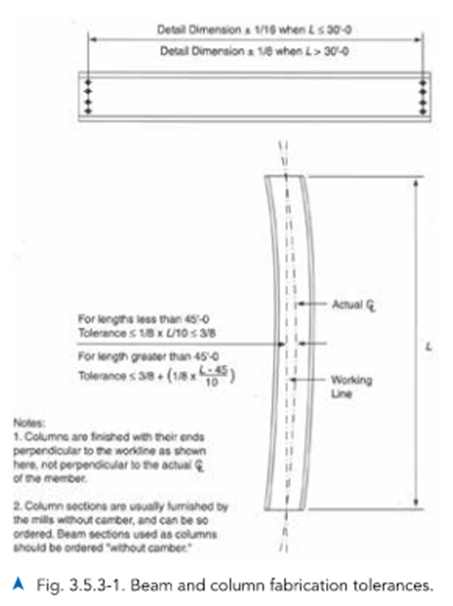
As an example of the effect individual member tolerances may have on the total structure, consider the tolerances on columns and beams. Individual column and beam members are shown with their respective permissible tolerances in Figure 3.5.3-1. These tolerances come from several sources:
- ASTM A6/A6M and AWS D1.1/D1.1M: permissible camber and sweep
- AISC Code of Standard Practice: permissible variation from detailed length for members framed to other steel parts
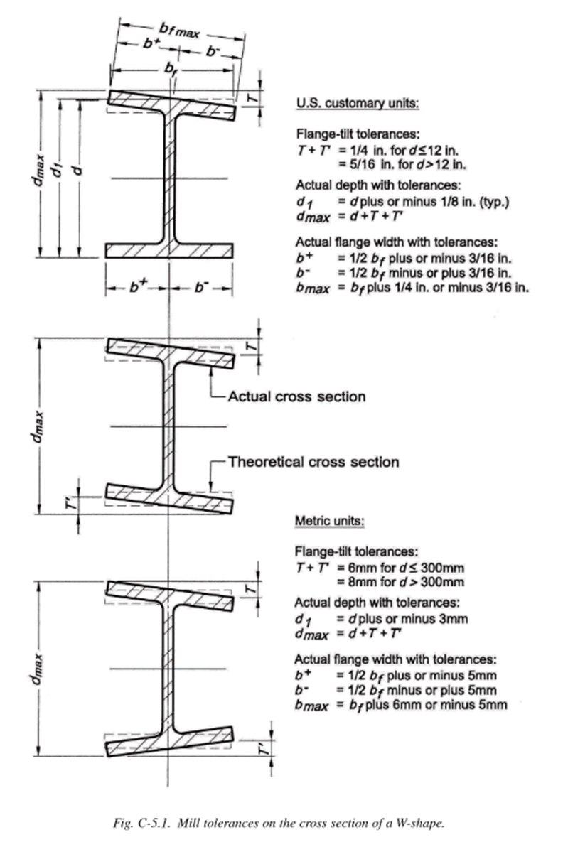
- AISC Code of Standard Practice Figure C-5.1: mill tolerances on the cross section
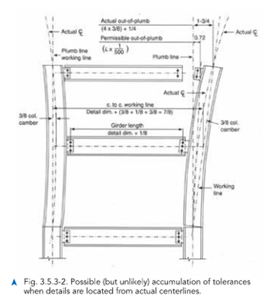
The following example involves a possible, but highly unlikely, scenario. A case where individual members fabricated within permissible tolerances could make it impossible to erect a heavy two-story column within the plumbness tolerance of ±1:500 is illustrated in Figure 3.5.3-2. Although the condition shown would be unusual and represents the worst case with all member tolerances maximized and accumulated in one direction, it is evident that the accumulation of tolerances requires special consideration.
Other possible examples include:
- double-angle and end-plate connections to columns
- attached shelf or spandrel angles
- large plan dimensions in which many pieces line up
- long bracing
- expansion joints
- vertical systems such as stairs and multistory wall panels
- deflections of cantilevered members and tolerance accumulation on complex framing systems involving a long series of connections before the load is in the column causing accumulation of vertical tolerances
Details for material supported by the steel framing must provide for the standard tolerances. For example, in buildings with large plans, it is beneficial to develop special details that accommodate the accumulation of fabrication tolerances. Note that building expansion joints cannot be adjusted to proper position without a provision for this adjustment.
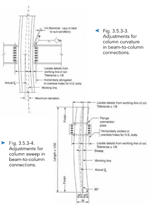
The use of oversized holes, short-slotted holes, and longslotted holes provides a satisfactory method for achieving erection within tolerances, as illustrated in Figures 3.5.3-3 and 3.5.3-4. Other satisfactory methods include the use of finger shims, shop layout to theoretical working lines, and recognition of tolerance accumulation in details for finishes, such as the façade attachments. See AISC Design Guide No. 22: Façade Attachments to Steel-Framed Buildings for further information.