Steel Solutions Center
8.2. Groove Welds
8.2.1. Are weld quality criteria applicable to the root area of partial-joint-penetration groove welds?
Sometimes. Fusion and sound weld in the root of sharp grooves can be difficult to reliably achieve. Therefore, many of the joint details approved for prequalified PJP (partial joint penetration) WPSs (welding procedure specification) limit the effective weld size to a depth less than the groove depth, usually by 1/8 inch. This ‘loss’ can be dependent on the welding process and position. Acute heels in tubular Y-connections and K-connections have a ‘backing pass’. That 1/8 inch or backing pass is not expected to meet volumetric inspection criteria.
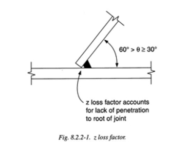
8.2.2. When a weld is placed between plates forming an angle that is less than 60 degrees, why is a Z loss factor applied to determine the effective throat?
The Z loss factor is applied at angles below 60 degrees to recognize that this weld cannot reliably penetrate to the root of the joint and is thus a partial-joint-penetration groove weld; see Figure 8.2.2-1. Note that, below 30 degrees, this joint is no longer prequalified and is not considered is strength calculations. See AWS Clause 4.4.3.3 and 4.4.3.4 for more information.

8.2.3. What is the difference between a flare weld and a partial-joint-penetration groove weld?
A flare groove weld is a special kind of partial-joint-penetration groove weld wherein the convex surface of the connected part(s) creates the joint preparation.
8.2.4. What purpose does a weld access hole serve?
The primary purpose of a weld access hole, as the name implies, is to allow the welder access to start and stop the weld beyond the plane of a beam web or other obstruction. At the same time, the weld access hole also reduces restraint to allow for shrinkage in the welded joint and eliminates the intersection of welds in orthogonal directions (and the associated intersection of stresses).
8.2.5. When should weld tabs and backing bars be used and when should they be removed after welding? What are shelf bars?
Weld passes do not start or stop with a smooth face normal to their axis. Starting in or ending in a plate normal to the weld axis (a dam) can result in a planar termination but this has historically been considered bad practice. The concern is that a lack of fusion, slag, and crater cracks will be buried in the weld terminated in this fashion. Where this is a concern, weld tabs extend the weld beyond the required length of the weld.
Backing supports molten weld metal in joint details with root gaps. Shelf bars are strips of metal used to thicken lower members to support a weld to an upper member. Shelf bars have been a tool used by welders for many years but were only recently recognized in AWS D1.1.
All of these are bars added to support molten weld metal and provide sound welds. But their treatment and removal can be very different. Weld tabs are removed in seismic column splices at the outside ends of column flanges to continuity plate welds, and where their presence conflicts with subsequent construction details. Backing bars and shelf bars are removed where these interfere with subsequent construction details. Backing bars and shelf bars are more expensive to remove than weld tabs.
Explicit requirements for the removal of back-up bars and run-off tabs in seismic projects are included in the AISC Seismic Provisions ANSI/ AISC 341, AISC Prequalified Connections for Special and Intermediate Steel Moment Frames for Seismic Applications ANSI/AIISC 358 and Structural Welding Code-Seismic Supplement AWS D1.8/D1.8M. An exception is included for tested assemblies that can be demonstrated to have acceptable performance with alternative treatments.