Why Steel
Detailing Considerations
It's far easier to start a project with detailing in mind than it is to go back and take care of it later. Various building enclosure systems (or skins) have different connections to the many available steel framing systems, and you'll want to be mindful of how the two interface as you develop a project.
 Here, we'll identify common issues that should be addressed in the early phases of a project. Bear in mind that each project and region will have different considerations when it comes to creating a weather-tight enclosure system.
The type of lateral system used in a building may have a large impact on the location of the enclosure's interior face relative to the column centerlines. If an exterior wall has diagonal bracing, the enclosure system and the interior wall finish, along with any supports, must clear the bracing members.
Usually, these bracing members are rods, angles, or structural tubes (hollow structural sections, or HSS) that are located on the column centerlines. If single angles are used, the vertical leg of the member is generally attached to a gusset plate that is located directly on the column centerline. The horizontal leg should be oriented so as to avoid interference with the enclosure system, its back-up system, and the interior wall finish.
It's important to note that bracing is not required in every bay if a system uses cross-bracing. Depending on the building size and configuration, bracing may only be required in one or two bays in each primary direction of the building. Cross-braced bays can sometimes accommodate doors and windows within the bay, provided the opening's frames and supports clear the bracing members and associated connections.
You'll have more design freedom in terms of placing the enclosure or interior wall finish surfaces if the building's lateral system uses rigid moment frames or shear walls. There are, however, cost implications and detail considerations that must be addressed if alternate lateral bracing systems are used.
 The following details show a floor system that comprises a steel floor deck topped with concrete. Typical floor system thicknesses range from 4 in. to 7 ½ in. depending on floor loads, the distance that the system must span between beams, and the required fire rating.
There are two varieties of cold-formed steel floor deck: composite and non-composite. A composite deck has dimples pressed into its surface. Those dimples interlock with the cured cast-in-place concrete to form the tension reinforcing in the bottom of the slab. A composite steel floor deck acts as a permanent form and as the positive bending reinforcement for the structural concrete topping.
Non-composite steel floor deck acts as permanent formwork for reinforced concrete slabs. It is only a form; the deck does not have dimples, and it does not act compositely with the concrete.
Similarly, composite and non-composite steel beams can both support the floor system. Composite beams headed studs welded to the top flange of the member after the metal deck has been installed. These studs interlock with the cured cast-in-place concrete; the concrete and steel work together as a composite unit. Non-composite beams are standard steel beams that support the metal deck and concrete topping without any interlocking studs.
Composite beams are generally lighter and shallower than non-composite framing. It should be noted, however, that all floor systems should be carefully checked for any floor vibration concerns.
Steel framing can accommodate several other types of floor systems, including cast-in-place concrete and precast concrete planks. Precast planks can span 10 to 40 ft between steel girders, depending on the floor load and plank thickness, but long spans of planks may require deeper steel girders.
Exterior Masonry Walls
A quick note: We'll use concrete masonry units (CMU) as the back-up system for the masonry details in this Guide; back-up systems can also use other materials such as metal studs.
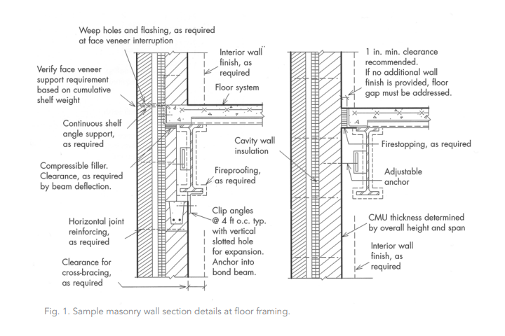
If you're considering a brick and CMU enclosure system, you’ll need to first determine the location of the entire enclosure system relative to the column centerline. The brick and block enclosure system can completely bypass the floor slab, perimeter beam flanges, and column flanges (Figure 1).
Alternately, the brick can bypass the floor slab, which will then support the CMU. Each system has advantages and disadvantages. If the masonry enclosure system bypasses the slab edge, the perimeter steel members do not support the load of the masonry at each floor, and therefore those steel members may be lighter and shallower.
The disadvantage of such an arrangement is that the weight of the entire enclosure system would be supported directly on the perimeter footings or grade beams. This may require a larger and more expensive foundation. In addition, the columns would project more into the interior spaces because they wouldn't be buried in the enclosure system at all.
The required clearances for the largest column or widest beam flange at the perimeter of the building will dictate the location of the inside face of the masonry enclosure system. In addition, masonry can only extend so high without intermediate supports. Please contact masonry industry professionals/publications for specific requirements and further guidance.
Precast Concrete Panels
Precast concrete panels can be an attractive and cost-effective enclosure system for some applications. Precast panel systems are most economical when the panel sizes are 20 ft to 30 ft in length, and the panel width/height is limited to approximately 14 ft.
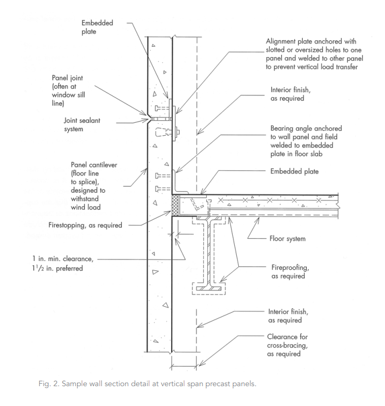
There are many ways to connect precast concrete exterior wall panels to the supporting steel frame (Figure 2). The precast panel manufacturer will generally determine the final details of the connection.
It is, however, the architect's responsibility to make adequate provisions for proper support and construction tolerance of the panels. Some precast manufacturers prefer to bear the panels on recessed pockets within the panels that are supported directly on seated connections or haunches from beams or columns. The seated connections or haunches minimize the eccentricity of the panel self-weight on the support connection. Other support options include such assemblies as structural angles or channels attached to the columns or beams which would support embedded angles located on the back of the precast panels.
Thin Stone Veneer Panels
Stone is a product of nature. As a result, thin stone veneer panels may have different physical properties--even stones from within the same quarry. For example, one granite panel may be as much as 150% stronger than another. When selecting a thin stone veneer system, it's important to carefully consider:
- the physical properties of the selected stone
- design criteria for the veneer
- the interrelationship of the exterior wall assembly
- the structural engineering responsibilities of the stone veneer and the anchoring system
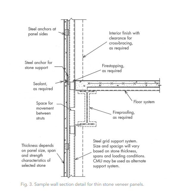
A grid strut back-up system will be required to laterally and vertically support the thin stone (Figure 3). This back-up system is generally a steel sub-frame system or a CMU wall. Please consult a stone fabricator for detailing information and deflection limitation criteria.
Because stones vary in strength, you need to pick stone panel anchors very carefully. A stronger stone requires fewer anchors, as the stone can support itself between them. There are hundreds of different anchors that are inserted into a kerf or slot cut into a hole drilled into the sides or rear of the stone panels. Choosing the appropriate anchor, based on the panel size, thickness, and back-up system is critical to the success of thin stone veneer panel systems.
Curtain Wall Enclosure Systems
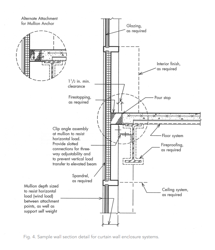
Window wall and curtain wall systems contain their own lateral load-resisting structural system. The glazing systems' mullions provide support to transfer the exterior wind loads on the glazing to the primary building structure. Generally speaking, the glazing horizontally or vertically spans the short direction between mullions, depending on the proportions and orientation of the glazing (Figure 4). Please consult a window wall manufacturer to determine practical mullion locations and depths. It should be noted that mullions can generally be reinforced with steel to increase their strength without increasing their depth.
Floor Assemblies
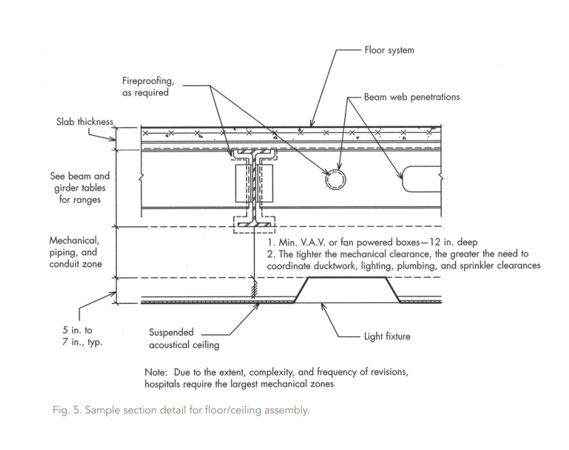
Evaluating space requirements for mechanical, electrical, plumbing, and fire suppression systems can be difficult to do at the beginning of a project. Unfortunately, that is when decisions about overall building systems need to be made. Probably the most important system decision to be made is to determine the approximate space the mechanical ductwork will require within the ceiling cavity. A mechanical engineer consultant will provide the most accurate information in the early phases of the project. General locations of major ductwork or piping crossovers should be identified (Figure 5). Crossovers can be the type of problem area that require lowered ceilings and expensive beam web penetrations if sufficient space is not provided when the ceiling plenum depth is determined.
Cross-Bracing Details
Buildings that incorporate cross-braces within the lateral system can be extremely economical. However, the braces themselves may conflict with ideal locations for doors or windows. In order to minimize any sort of conflict between the bracing and the doors/windows, it is important to understand exactly what shape/section the brace member is and where it is located.
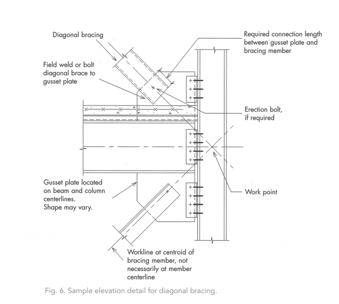
It's best to bring the work lines of all connecting members together at one work point (see Figure 6). Ideally, the work lines run through the centroids of all the members. If the member is not symmetrical (for instance, an angle instead of a wide flange) then the work line is not at the mid-depths of the member because the centroid of an angle is not at the mid-depths of the member. This is essential to understand when determining whether or not a window or door frame will bypass the brace.
Gusset Plates: Fabricators produce gusset plates in a variety of sizes and shapes. The force in the cross-brace and the thickness of the gusset plate will dictate a gusset plate’s minimal dimensions. The degree to which the brace and gusset plate must overlap to achieve the required connection strength will determine the minimum size of the gusset plate. If the gusset plate is hidden within a wall, the size and shape of the gusset plate generally is not an issue. However, if the gusset plate is exposed, there are virtually endless possibilities for its shape.
Work Lines: The work line for the bracing member is located at the centroid of the bracing member but it may not necessarily be at the mid-depth of the member. This would be the case for non-symmetrical members such as WT and angle shapes. Also, the angle of the bracing member at a floor may be at a different angle from a floor above or below it. This would occur if a building had varying floor-to-floor heights.
Bracing Members: Bracing members can consist of virtually any structural shape. Typically, rods, single angles, double angles, WT shapes, and hollow structural sections (HSS) are used as bracing members in tension. Sometimes, wide flange shapes are used if the bracing forces are extremely large.
Work Point: The work point is the intersection point of the work lines. It should be noted that it is desirable, but not always necessary, for the work lines to intersect at a work point. If the work lines do not intersect at a work point, the connections must be designed for these eccentricities and you may ultimately need larger members. Please consult a structural engineer for further details in this situation.