Why Steel
Guide to Using the Preliminary Beam, Girder and Column Size Tables

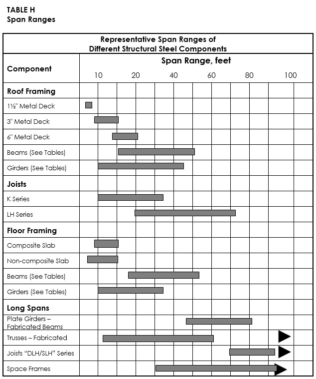
During the early stages of a project, before a structural engineer is engaged, architects frequently need to get a sense of the required column sizes and beam/girder depths that might ultimately be required for their projects. While this tool is not a substitute for structural engineering services, the American Institute of Steel Construction (AISC) has developed a series of tables to aid the architect in determining approximate column sizes and floor and roof system depths (Table sets A, B, C, D, E, F, G, H, I, J, and K). Each set of tables represents a distinct set of floor and roof system parameters. Three different “live load” (example: people and non-permanent load) conditions for each range of beam and girder spans have been presented. The tables present nominal member depth ranges (example: W24 beams have a nominal depth of 24") for beam spans of 15 feet to 45 feet, as well as girder spans from 15 feet to 45 feet. Preliminary beam and girder depths can quickly be determined from the tables for square and rectangular bay sizes ranging from 15'x15' to 45'x45'.
The beam and girder depths indicated in the tables represent a range of depths for a particular span. It must be brought to the user’s attention that a shallower member depth generally results in an increase in member weight, and therefore increased cost. As a general “rule-of-thumb” a 25 percent increase in member weight will occur with each size of depth reduction. For example, if the reported range is W18 – W24 there will be an approximate 25 percent increase in weight for a W21 member to meet the same design criteria as a W24. A W18 member will have an approximate 25 percent increase in weight if selected in place of a W21. Should a W18 member be selected in place of a W24, the minimum increase in member weight will be approximately 60 percent (1.25 x 1.25).
As with any design problem there are many solutions. Each project will have a unique set of loading and serviceability (deflection and vibration) parameters. The design information and example have been prepared accurately and consistently with current structural design practice for multiple load cases. The information presented in this publication has been prepared in accordance with recognized engineering principles and is for general information only. While it is believed to be accurate, this information should not be used or relied upon without competent professional examination and verification of its accuracy, suitability, and applicability by a licensed professional engineer or architect.
Design Parameters and Limitations
Many specific parameters and limitations go into the design of any structural member. Loads imposed by earthquake, wind, snow, rain, construction methods, etc., vary across the country. Live loads are generally specified in the applicable building codes. Dead loads are much more variable and require special attention in their computation. Specific requirements for strength, serviceability, lateral stability of individual elements, and the lateral resistance of the overall building all contribute to the design of a safe and efficient building. The information presented in the following tables is intended for use in establishing preliminary floor and roof framing member depths only, without regard to earthquake loading or contributing to lateral resistance of the building.
Beam spans in these tables range from 15-feet to 45-feet, in 5-foot increments. Girder spans also range from 15 feet to 45 feet in 5-foot increments for each of the beam spans noted. Therefore, beam/girder depths tabulated cover 28 different bay sizes for each of three load cases. Dead loads address the self-weight of the floor/roof framing system. Different topping-slab thicknesses, concrete densities, and beam spacings options have been presented to address varying preferences around the country to address required floor/roof fire rating requirements as well as local availability of concrete aggregate.
The following girder and floor beam sizing tables are based on the following parameters:
- Load and Resistance Factor Design Specification, American Institute of Steel Construction, 2017
- Live and dead loads are uniformly distributed over the entire bay area
- Full live load has been applied to a full bay; no live load reduction has been taken into account
- No analyses have been made for floor vibration/vibration susceptibility
- A construction live load of 20 psf has been applied for composite member design
- Beam and girder depths represent designs for composite beams and girders (non-composite beams/girders would likely be slightly deeper)
- Live load deflection has been limited to 1/360 of the individual member span
- Shear connectors for composite type metal decking
- Normal weight concrete unit weight used in the designs is 145 pcf; Lightweight concrete unit weight used in the designs is 110 pcf
- Beams and girders have been selected assuming that cambering will be considered by the structural engineer of record for the placement of “level” floors
- Connection designs have not been considered
- 50 ksi steel yield strength and 3000 psi concrete strength
- Actual member depths may vary from the nominal depths tabulated. For actual member depths refer to the properties tables found in the ?? Section of this Guide.
Selection Example for Girder and Floor Beam Sizing Tables
Known Design Criteria:
- Dead load equals system self-weight (slab + steel)
- Superimposed dead load = 25 psf (partitions + MEP)
- Live Load = 100 psf (loads are uniformly distributed over the entire bay area)
- 4¼" Lightweight concrete topping
- 2" metal decking (composite)
- Fy=50 ksi
- Floor system requiring a 3-hour fire rating (floor assembly, unprotected metal deck)
- Bay size is 30-feet x 35-feet (girder span x beam span)
- Beam spacing is 10-foot max.
Solution:
Beam depth selection:
Enter “Table C, Beam Sizes”, which is located directly below the illustrative floor diagram
Find the required 100 psf Live Load criteria along the left side of the table.
Slide over to the fifth column of the table to find the typical beam depth range for a 35-foot beam span. The range of beam depths is shown as W16-W18. Therefore, the table indicates that the nominal wide-flange beam depth for a 35-foot beam (10-foot max. spacing and supporting 100 psf live load) could be as shallow as 16-inches (indicated by W16) or as deep as 18-inches (indicated by W18).
Girder depth selection:
Along the left side of “Table C, Girder Sizes” (located directly under the “Beam Sizes” table), find the row for a 30-foot girder and a 100 psf live load.
Across the top of the table, find the column for a 35-feet beam.
At the intersection of the 30-foot girder row (100 psf live load) and the 35-foot beam, find that the range of girder depths to support the 35-beams spaced at 10-foot max. as W21-W24. This table indicates that the 30-foot long girder could be a wide-flange girder with a nominal depth as shallow as 21-inches (W21) or as deep as 24-inches (W24).
Summary:
35-foot beam span: W16-W18 (Note that actual depths will vary).
30-foot girder span: W21-W24 (Note that actual depths will vary).
Member cambers may be required (Consult a structural engineer for specifics).
Resources
Have a more complex situation?
Contact our Steel Solutions Center to begin your request for a free, customized conceptual solution for your project.
Steel Solutions Center