Why Steel
Lateral Systems
You should start thinking about the lateral load-resisting system(s) in your project early in the planning phase.You'll also want to bring in your team's structural engineer early to can determine which type of system will work best for your specific building height and configuration and specify where the system should be located.
You'll work closely with the structural engineer to balance the lateral resistance requirements of the structure with your architectural vision.
One project may use multiple types of lateral systems because each system has its own strengths, limitations, and potential architectural implications. There are three common types of lateral resisting systems: braced frames, rigid frames, and shear walls.
Braced Frames - General
There are several variations on the braced-frame model, using cross-brace, chevron brace, inverted chevron brace, and eccentric brace systems. The chevron and inverted chevron braces can be stacked to create a striking two-part cross-brace like those seen on 875 N. Michigan Avenue in Chicago.
The location of doors and/or windows on the braced frame frequently determine the bracing configuration for the structure.
Eccentric bracing can help dissipate seismic forces through the beam or girder and therefore is commonly used in areas with a lot of seismic activity.
Braced frames are generally more cost-effective than other lateral systems.
Cross-Bracing
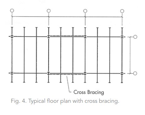
The cross-brace frame, represented in Figures 4 and 5, is perhaps the most commonly used system. Figure 4 shows a typical floor framing plan with cross bracing denoted by the dashed-line drawn between two center columns. The solid lines indicate the floor beams and girders.
Figure 5 depicts a typical multi-floor building elevation with cross-braced bays beginning at the foundation level. While Figure 5 shows only one bay of bracing, the height and size of the specific structure may call for bracing multiple bays along a given column line. As with all braced-frame configurations, it's important to establish the location of these bays quite early in a project's development.

Each intersection will have a common "work point" at which the centerlines of a column, beams, and diagonal members intersect. Gusset plate connections are used to join the steel members because all of them can't physically intersect at the work point. Figure 6 illustrates a typical beam-to-column joint for a cross-braced frame.
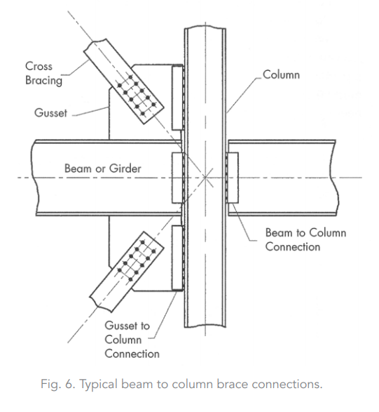
When a building exceeds two or three stories, the diagonal members may support substantial loads that require large gusset plates to placed directly next to the column and beams. These plates can take up space that may otherwise be required for mechanical and plumbing systems as well as architectural soffit details. To avoid costly field revisions during construction, it's important that the structural engineer provide the architect with information about the approximate size of the gussets in the planning phase.
Cross-braced bays make the most of steel's strength in tension to efficiently use small structural shapes. When a tension-only cross-braced system experiences a horizontal force from wind or a seismic event, only one leg of the cross-brace will provide resistance. When the load comes from the opposite direction, the other leg will become active in its place.
Chevron Bracing
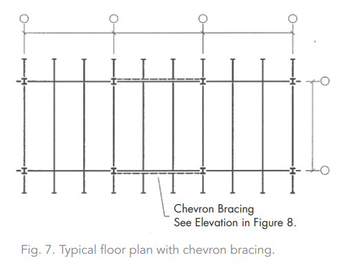
Chevron bracing is a modified brace-frame form that generally allows for doorways or corridors in the center of the bays.
Figure 7 shows a typical floor framing plan with the bays using chevron bracing, as denoted by the dashed-line drawn from between the two center columns. The solid lines indicate the floor beams and girders. Figure 8 shows a typical multi-floor building elevation using chevron bracing.

Gusset plates (similar to the cross-brace elements shown in Figure 6) typically connect chevron brace elements to associated beams and columns. The members can be either welded or bolted together, depending on processes at the steel fabrication shop or aesthetic considerations.
In situations where the chevron brace diagonal members attach to the structure above, the layout and coordination of mechanical ductwork and utility piping above the doorways and corridors must account for the depth of the gusset plate connection.
This bracing configuration subjects members to gravity compressive loads. Each of the bracing members is considered active in the analysis of the system when lateral loads are applied. As a result, the bracing elements experience both tensile and compressive forces.
Eccentric Bracing
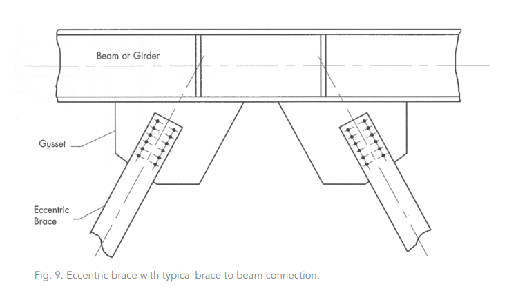
Eccentrically braced frames are very similar to chevron-braced frames. In both systems, the general configuration is a rotated "K" shape with the brace connected to a column and to the beam/girder at the level above. However, brace members intersect at the same point in a chevron-braced frame; that is not the case in an eccentrically braced frame. You can see this condition in Figure 9.
An eccentric brace is commonly used in seismic regions where a structure must have a significant amount of ductility or energy absorption. The segment of beam/girder located between the diagonal bracing member is designed to "link" the diagonal braces and help the system resist lateral loads caused by seismic activity. An eccentrically braced system is typically more expensive than a traditional chevron brace system because it uses larger beams and girders and because the brace connections are more complex.
Rigid Frames
Rigid frames, or moment frames, are used when the architectural design or some other constraint does not allow for diagonally braced frames. This type of lateral resisting system incorporates rigid welded or bolted connections between the columns and the beams/girders. Rigid frames are generally more expensive and less efficient at resisting lateral loads than a braced-frame system. However, low-rise building spans frequently use rigid frames when the bays can't accommodate diagonal braces.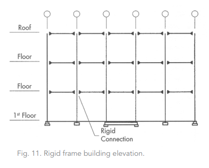
It's best to have well-proportioned bays with shorter span beams to manage building drift. This is one of the challenges of working with a rigid frame system.
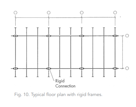
Figures 10 and 11 show a floor plan and building line elevation representing a rigid frame system. Figure 10's solid "triangles" are typically used to indicate rigid connections between the steel components. Figure 12 shows a typical moment connection between the beam/girder and a column; these connections typically use a shear connection along the web to support the gravity loads on the member, as well as field-welded beam-flange to column-flange connections to resist lateral loads.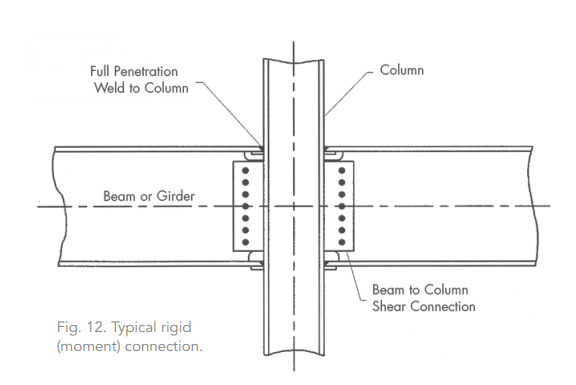
Rigid frame moment connections can be four to six times as expensive as a typical gravity connection because they require more preparation time and field welding. Column stiffener plates are sometimes required, at additional cost, between the flanges of the column to prevent buckling of the column webs.
Sometimes, when the forces are relatively small, it's possible to use a bolted endplate moment connection in place of a field-welded moment connection. It is important to note that this type of joint requires that all vertical utility ductwork and piping be free and clear of the column and beam/girder flanges. With a rigid frame, you generally want to avoid modifications to the beam/girder flange, such as coping or web openings to allow passage of piping or other utilities. The structural engineer on your team is a good resource in situations that may call for such modifications.
Shear Walls
This type of lateral load-resisting system engages a vertical element of the building, usually concrete or masonry, to transfer the horizontal forces to the ground by a primary shear behavior. Shear walls are inherently stiff elements and are therefore extremely effective at resisting lateral wind loads. Steel shear walls are also now available, as well as composite plate shear wall cores for tall buildings that use a non-proprietary system called SpeedCore. The SpeedCore system can significantly increase the speed of erection, and that shorter construction time can save a significant amount of money. Visit aisc.org/speedcore to learn more about this revolutionary core system.