AISC
Ballston Quarter Pedestrian Walkway
Merit Award - Less than $15 Million
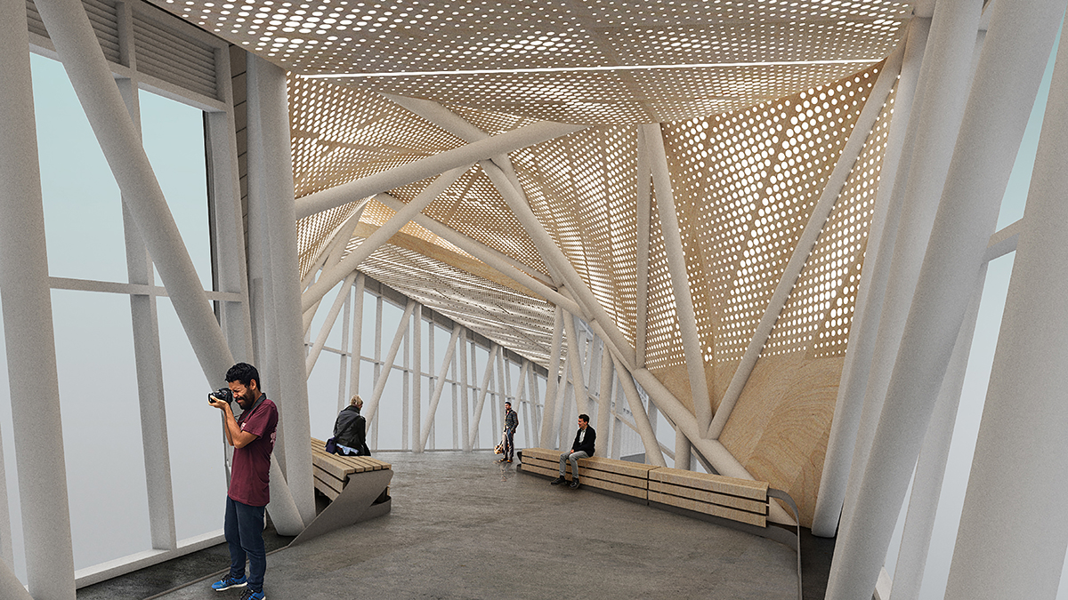
The crossover segment at mid-span creatively addresses the offset entrances of the connected buildings, and the steel HSS frame is an ideal choice to resist the complex forces of this innovative bridge design. The resulting structure has a sculptural quality that is visually captivating from both the exterior and interior. —2021 IDEAS² Judge Stephanie J. Hautzinger, SE, AIA, Associate Vice President, CannonDesign, Chicago
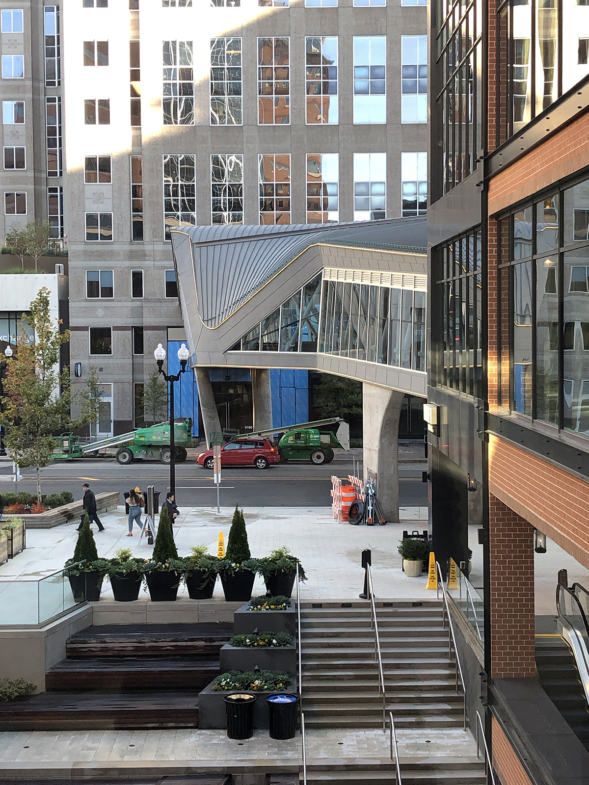
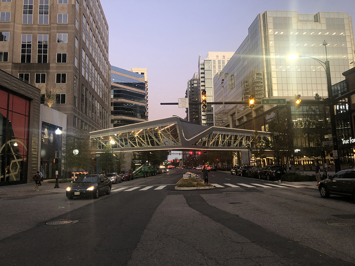
The Ballston quarter pedestrian walkway is intended to be an iconic structure while also blending into the surrounding streetscape in Arlington, Va.
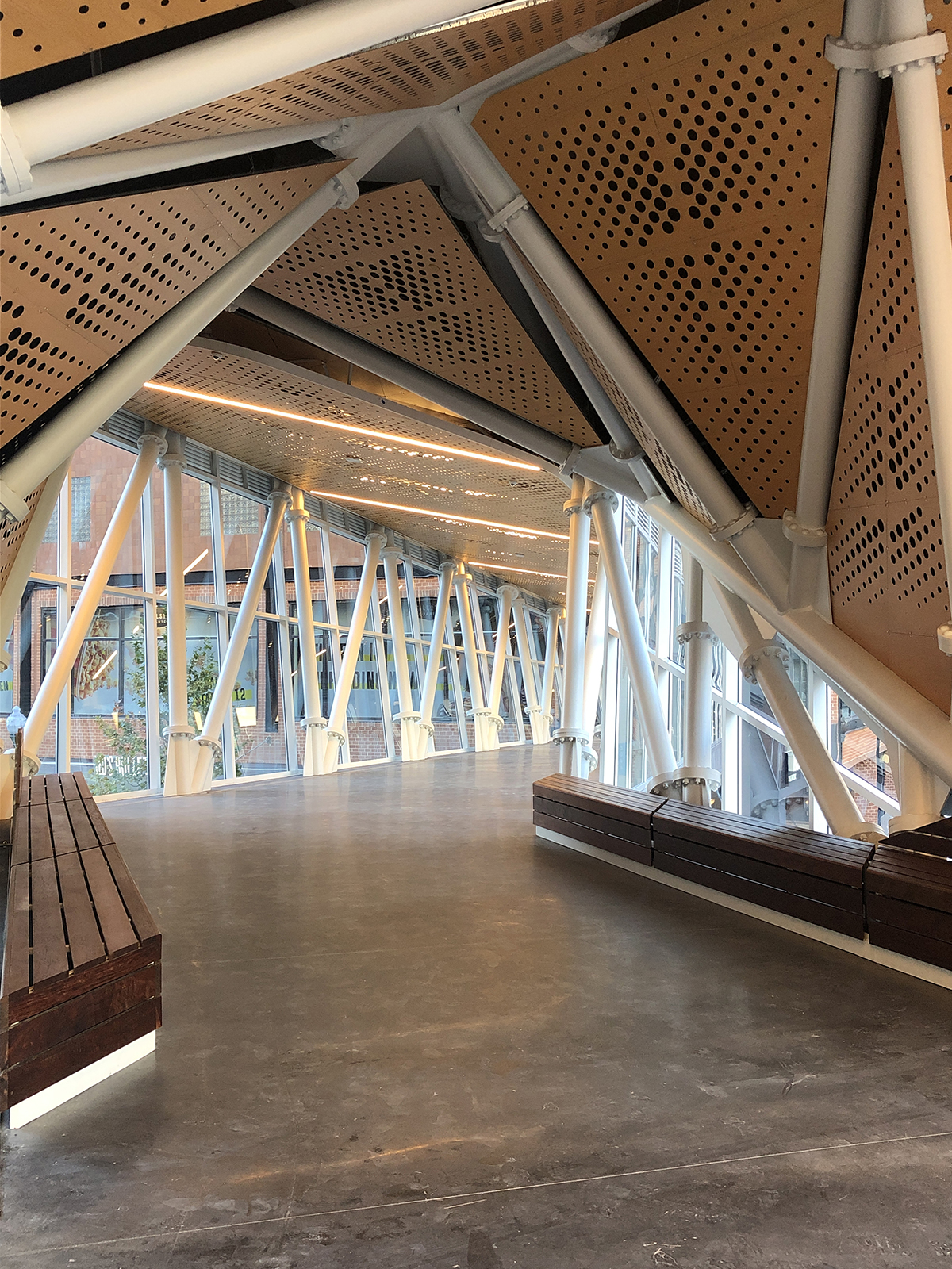
The design features a direct geometric approach, where the eccentric structure of the walkway oscillates between the wall and roof. The lines that comprise the structure and the transparent glass planes of the walkway engage the occupant, allowing an exploration of the transcendence of line and plane to provide a minimal sense of enclosure. This planar convergence transforms the experience of crossing the street, establishing unique view corridors and allowing participants to both observe and be observed as they move from private space to the public realm. Additionally, the walkway provides a direct connection to the DC Metro system, allowing people of all ages and physical abilities to access public transportation.
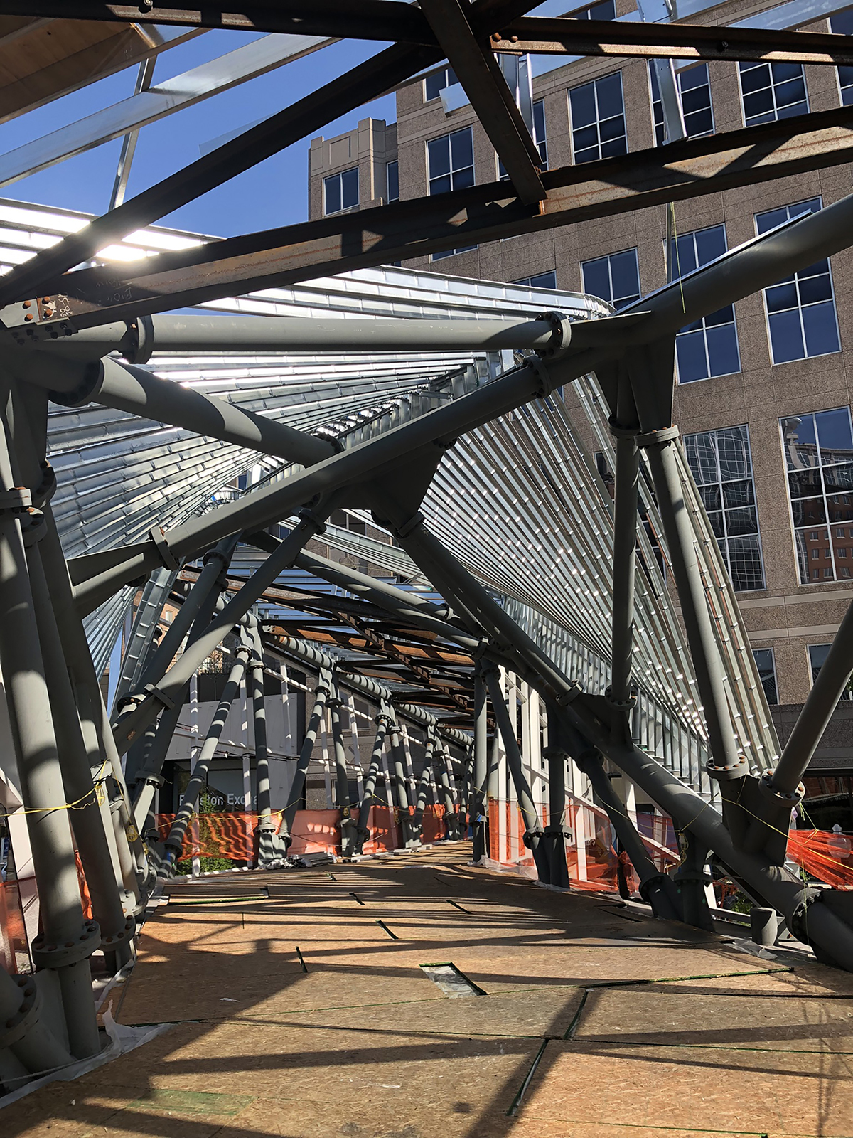
The steel-framed pedestrian crossing’s design began with the investigation of various arrangements and configurations while crossing Wilson Boulevard and the way it connects the two buildings on the north and south ends. The entrances into the terminal buildings were approximately 155 ft apart and were offset from each other. The main goal was to avoid a design whose axis would be at a distinctive angle to the Wilson Boulevard. Therefore, the axis of the overpass required a crossover segment near its mid-span. The concept from the beginning was to enclose the overpass with glass and expose as much of the structure as possible. The decision was made to use round hollow structural sections (HSS) for the superstructure, both for their aesthetic value and also for their ability to resist the complex torsional, shear, and bending stresses in addition to all gravity loads.
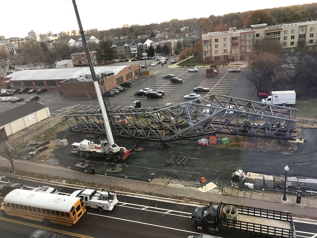
The project site crosses one of the most heavily traveled streets in Arlington County, Va., and early on, the County placed significant restrictions on any closure of the street to vehicular traffic, which effectively eliminated the opportunity for the walkway to be constructed on-site. The site was also challenging due to the lack of a laydown area adjacent to the walkway location. These conditions required the design and construction teams to implement a design strategy that allowed the walkway to be fabricated, disassembled, shipped to a closed public park two blocks away, reassembled, and moved through the city streets as a single structure into its permanent position.
Additional challenges were presented by the building at the north terminal of the walkway, which had several levels of underground parking. A successful design solution required the walkway to impose no soil pressure on the foundation wall, as well as the development of a structural solution that allowed the walkway to rest with almost no imposed load on the two adjacent structures. Underground electrical duct banks feeding the majority of the adjacent buildings also limited the placement and design of the foundation system. A structural steel frame on concrete piers was the only solution that allowed the project to cantilever to the existing buildings, impose minimal loads, and maintain the necessary rigidity to minimize deflection and bounce for pedestrians traversing the walkway.
Expansion and deflection of the 155-ft-long walkway were also concerns. The calculated ideal air temperature for the final tightening of the bolts at the bearing points was 70 °F, which occurred a few weeks after the hoisting of the frame, at which time all bolts were tightened and welding at the bearings was completed. The casting of the concrete floor slab followed, and the deflection of the frame was monitored; it ended up matching the deflections predicted by the design calculations. Construction continued by architectural, mechanical, and electrical trades, and the iconic overpass began to take on its final appearance.
studioTECHNE Architects established the preliminary shape of the superstructure by defining the 3D locations for the main geometrical nodes. The geometry was subjected to large overall bending moments, shear, and torsional forces generated by gravity loads, wind pressures, and seismic forces that the individual members had to safely resist. The overall deflection was minimized to allow as much clearance as possible underneath the overpass for vehicular traffic on Wilson Boulevard. The unconventionally large floor area of the overpass and the large volume of the expected pedestrian traffic over made it necessary to structurally minimize perceptible vibration of the floor deck and to minimize wind-induced lateral movement on the entire superstructure. The four leaning concrete piers created some additional reactions on the superstructure and also imparted reactions into the superstructure, requiring fixed connections between the piers and the superstructure. In addition, thermal expansion and contraction had to be resisted by the same connections.
A “spine” was designed to act as a main supporting element that extended in a straight line in plan between the north and south ends of the superstructure, which became the largest steel element. Several other key elements were attached to the spine. The floor deck consisted of wide-flange girders along the two edges of the floor and beams with a composite metal deck and a concrete slab. The floor deck was designed as a diaphragm span from end to end and to resist the lateral wind and seismic loads and the associated torsional, shear, and bending stresses in addition to all gravity loads. Multiple rectangular rigid frames were designed to provide the required lateral stability of the superstructure’s cross section against lateral loads. The roof structure, consisting of HSS and wide-flange purlins as well as steel angle cross bracing, acts as a supplemental diaphragm maintaining horizontal stability of the roof and equalizes lateral loadings. The two wide-flange edge girders were designed to resist thermal and seismic forces in the length-wise direction of the floor diaphragm. The large dimensions of the superstructure required bolted moment connections for assembly consisting of circular plates with bolts.
To facilitate transportation and erection of the completed bridge assembly, LIDAR scanning was used to digitally scan the entire site and develop a 3D model of the existing conditions. This permitted the construction team to test a number of lift and placement scenarios through which the entire 140-ton structure would be picked and lifted into position. The design team provided a complete 3D model of the structure, which the construction team used to develop sophisticated computer simulations to test a series of possible angles of arrival, tilt, and yaw required for placing the walkway, finally settling on a single crane to make the lift.
Fabricator Crystal Steel completely assembled the walkway in its shop, and the bridge was scanned to ensure the control points, with the tolerances matching what was required. The walkway was disassembled, shipped to the site, and reassembled two blocks from its final destination. The erector was given the calculated location of the assembled segment’s center of gravity for proper hoisting and placement. Motion and deflection sensors were connected to the walkway to monitor movement, and it was then picked up, placed on Goldhoffer trolleys, and transported on the street to its final location. Owing to the precision of the planning and fabrication, the lift was executed as simulated, with perfect alignment of the walkway to the bearing plate assemblies.
Steel fabricator and detailer: Crystal Steel Fabricators, Arlington, Tenn. *AISC Member* *AISC Certified Fabricator*
Structural engineer: Peller + Associates, Westlake, Ohio
Architect: studioTECHNE|architects, Cleveland
General contractor: Clark Construction, Bethesda, Md.
Owner: Brookfield Development, Washington, D.C.
- Project Category: Year 2021
- Location: Arlington, VA
- Award Category: Merit Award - Less than $15 million
- Year Completed: 2019
- Submitting Firm: studioTECHNE|architects
- Photo Credit: 1, 2, 4, 5, 6 - Marco Ciccarelli; 3 - studioTECHNE|architects