AISC
Belmont Gateway Canopy - Chicago Transit Authority
Merit Award - Sculptures/Art Installations/Non-Building Structures
Aesthetically, the design bridges the urban setting with nature by incorporating elements of a bygone park from the area. —2020 IDEAS² Judge Hollie Noveletsky
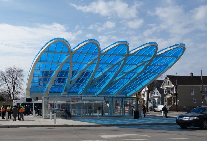
Fifty years after it was built, the Belmont Blue Line Station has been transformed into one of the most recognizable stations in the Chicago Transit Authority’s (CTA) vast rail system.
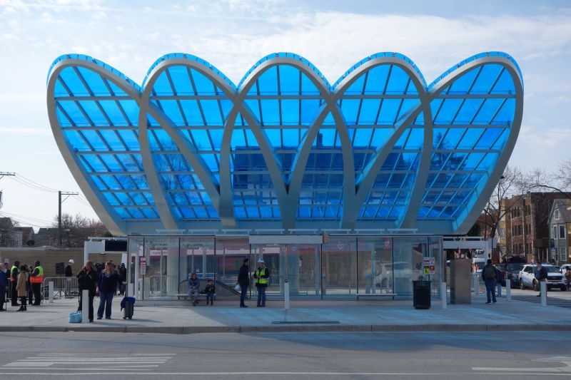
Upgrading the entrance provided an opportunity to improve the station’s visual presence and create a community focal point within Chicago’s Avondale neighborhood. The design, inspired by a waterfall from the bygone Olson Park, becomes “animated” when it rains as water cascades down the sloping canopy.
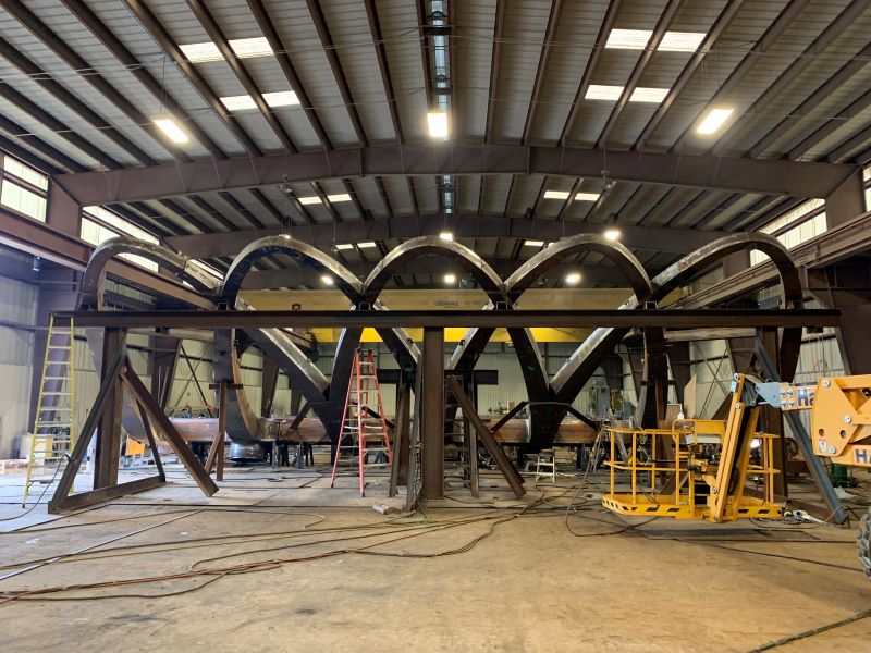
The canopy structure is formed by five petal-shaped, architecturally exposed structural steel (AESS) frames that cantilever 68 ft over the station’s plaza and 28 ft in the other direction. AESS emphasizes the overlapping outlines of the petals without adding unnecessary cladding. The primary framing members that form the outline of the petals are built-up rectangular tube sections that support hollow structural section (HSS) purlins that connect to the canopy’s blue polycarbonate panels. The petals frame into a horizontal spine at the low point of the slope with custom castings that are supported on three 38-in. steel-encased concrete pipe columns concealing the drainage downspouts within the concrete.
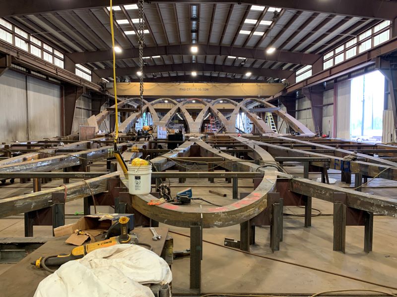
The canopy’s geometry required the primary structural framing members to be curved in one dimension, sloped in a second dimension, and tapered in the third dimension. The project team was able to simplify fabrication through creative design and by evaluating how the geometry influenced the strength requirements. The primary HSS framing members efficiently resist biaxial and torsional stresses. Rectangular shapes were selected because they are more commonly used in the U.S. and are easier to connect. Plates were cut into trapezoids, curved, and welded together to form the curved tapering sections. Cast steel nodes were selected for the complicated moment connections where the petal loops meet the spine as a means to adequately resist the forces, simplify construction, and meet aesthetic requirements.
The overall structural system includes the cantilevered canopy—which accounts for more than 90% of the project’s total weight (approximately 162 tons)—supported on three columns. A network of primary framing members provides stiffness to control deformations and is anchored to the ground with large concrete-filled steel columns that act as “tree trunks” to support the overlapping steel “branches” of the canopy.
To transfer significant biaxial bending forces and torsion into the columns, accommodate the downspouts concealed within the columns, and provide access to place the concrete in the columns, the design team worked closely with the cast steel designer and supplier Cast Connex to develop customized cast-steel connection nodes. Coordinating this design decision early in the schematic phase allowed the project team to evaluate the connection’s ability to meet the required demands of the structure and provide confidence to the design team and CTA that the project vision would not be compromised within future phases of the job. In addition, minimizing the disruption to the surrounding area was important to CTA and the project team. A deep foundation system with small-diameter drilled piers was chosen to bypass existing below-grade structures and limit the effects on the adjacent street, active bus routes, and subgrade trains.
This design-build project provided many opportunities for the design, casting, and fabrication teams to collaborate. Bringing these parties together early allowed the project team to work together to develop creative, efficient, and successful solutions. The design team used 3D and structural analysis models to coordinate and evaluate this complex structure, as well as to help facilitate information sharing. Architectural models developed in Rhino 3D were incorporated in the structural analysis model, while customized software packages were used to automate portions of the analysis and evaluate numerous iterations and structural variables: the size of the AESS framing, considering the varying cantilever lengths; framing plans (e.g., numbers of columns, petals, and intersecting petal nodes); plate thickness for the primary petal framing; column diameters and thicknesses; and the amount of welding required. The automated parametric structural analyses enabled the design team to analyze stresses and deflections for each combination of options and achieve the aesthetic goals while helping to minimize fabrication and erection costs.
The cantilevered boxed sections were fabricated out of 2-in. 50-ksi steel plate with mostly complete joint penetration (CJP) welds. AESS requirements reduced tolerances by half, minimized joint gaps, and stipulated that all welds had to be continuous with a uniform and smooth appearance within close visual proximity.
Steel fabricator and detailer: King Fabrication, Houston *AISC Member* *AISC Certified*
Steel erector/general contractor: The Walsh Group, Chicago *AISC Member* *AISC Certified*
Steel casting supplier: Cast ConneX Corporation, New York *AISC Member*
Architect: Ross Barney Architects, Chicago
Structural engineer: EXP, Chicago
Project ownership: Chicago Transit Authority, Chicago
- Location: Chicago, IL
- Award Winner Year: 2020
- Year Completed: 2019
- Submitting Firm: Simpson Gumpertz & Heger (SGH)
- Photo Credit: 1 - 5: Ross Barney Architects