National Steel Bridge Alliance
I-91 Interchange 29 Exit Ramp Flyover
2022 Bridge of the Year
National Award -- Medium Span
Engineering Challenges
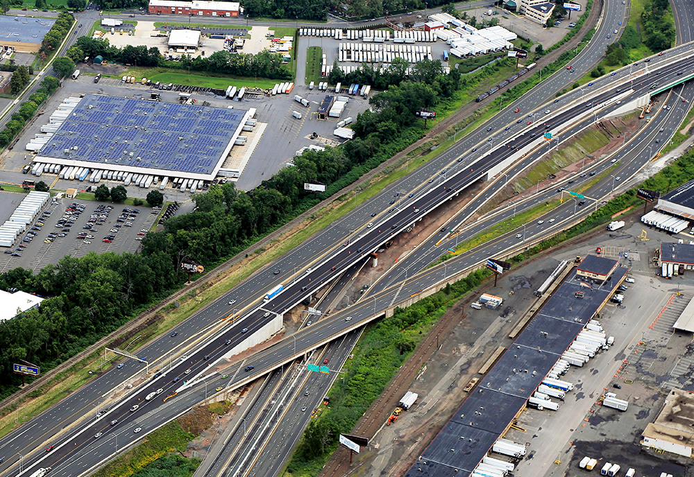
The project focused on a long-term problem with congestion at Interchange 29, which connects I-91 Northbound with Route 5/15 in Hartford, CT. Route 5/15 is the major connector between I-91 and I-84 in East Hartford. The original ramp was a single-lane ramp with a steep grade and a significant traffic weave at the intersection with Route 5/15. This resulted in significant daily back-ups on I-91 that led to numerous accidents and delays. Improvements to the interchange were one of the top priorities of the Connecticut DOT. The reconfiguration of the interchange resulted in a new high-speed two-lane ramp that crosses over Route 5/15 Southbound in a weave configuration. The interchange 29 ramp bridge presented several significant engineering challenges. The new ramp is a straight ramp that crosses a curved roadway at a very flat angle, resulting in significant geometric impacts to the roadway below.
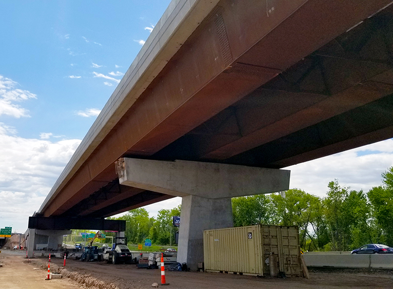
The first challenge was a result of the need to have the traffic below pass very close to several of the bridge piers of the new bridge. The vertical geometry of the roadway below the bridge limited the ability to pass vehicles underneath the proposed hammerhead pier caps due to low vertical clearance at the hammerhead piers. There were three potential solutions: raising the bridge (not feasible), lowering the roadway (not possible), or reducing the pier cap's width. The use of trapezoidal box girders allowed the design team to locate the bridge bearings closer to the centerline of the bridge, thereby reducing the width of the pier cap by 8 feet. This is an advantage of box girders that designers often overlook. The reduced cap width also reduced the cost of the piers by reducing the volume of concrete and the bending moments acting on the shorter cantilevers.
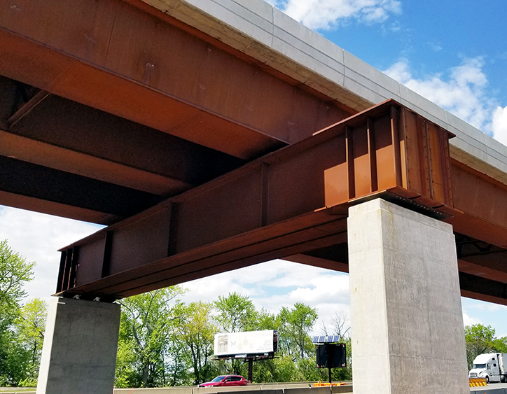
The second challenge occurs where the two roadways intersect. The extremely flat angle between the two roadways can be accommodated in several ways. The first is a long span between piers. The design team investigated this; however, the required span was over 400 feet, which was not feasible at the site. The second way to accommodate a severe skew is to use a straddle bent. Straddle bents are quite common in high-speed interchanges. There are several challenges straddle bents. First and foremost is the designation of steel straddle bents as fracture critical members. This increases future inspection costs. For this reason, concrete straddle bents have been used in many states; however, there are limitations to the use of concrete for long-span bridge crossings.
The design team was well aware of the recent work by NCHRP, AASHTO, FHWA, and NSBA on the redundancy of steel bridges. This includes the investigation of System Redundant Members, Internally Redundant Members, and Load Path Redundant Members. The goal was to design a "Load Path Redundant" steel straddle bent. The following sections will cover this special design in more detail.
Unique Attributes
The Interchange 29 ramp bridge is the highly visible centerpiece of the interchange project. There was a desire to make the bridge aesthetically pleasing with clean lines and uncluttered framing. The Connecticut DOT is very much in favor of the use of uncoated weathering steel. It is the first choice of corrosion protection for highway overpasses, which is why it was selected for the Interchange 29 ramp bridge.
CTDOT has a long history with uncoated weathering steel, dating back to the early 1960s. Several Connecticut weathering steel bridges have won Prize Bridge Awards over the years. The Department recently completed a study of the performance of uncoated weathering steel. The performance of bridges with quality details was found to be very impressive. Some of the oldest uncoated bridges are still in very good condition after more than 55 years in service, reinforcing the state's preferred use of uncoated weathering steel.
The geometric layout of the bridge also improves its aesthetic look. The trapezoidal box girders without exterior stiffeners produce clean lines. When compared to vertical webs, the sloped webs have historically been the look of choice for bridge aesthetics. The sloping webs draw the eye toward the single columns supporting the pier caps, demonstrating a flow of forces from the superstructure to the ground.
Another major factor that makes this bridge stand out is the innovative design of the straddle bent. The goal was to design a redundant beam. The concept of "Load Path Redundant Members (LPRM)" was the approach used. FHWA presented a definition of Load Path Redundancy to AASHTO COBS in 2019 as follows: "A steel primary member in tension that has redundancy based on the number of main supporting members between points of support, such that fracture of one cross section of one member will not cause a portion of, or the entire bridge to collapse." FHWA further noted that "LPRMs are usually longitudinal and parallel, such as girders or trusses. Redundancy can be determined by engineering judgment or simple calculation. Primary members in common girder bridges with three or more girders are classified as LPRMs in most cases". The design of the straddle bent for the Interchange 29 ramp bridge is based on providing an LPRM design. This was accomplished by converting a typical single-cell box girder section into a three I-girder member. Simple details were developed to achieve this configuration. Plate diaphragms were designed using finite element analysis to distribute forces equally to each girder, and transfer load should one girder flange fracture. The team developed an “integral” or framed-in straddle bent concept and a "stacked" straddle bent with the superstructure on top. There was adequate vertical clearance at the straddle bent location to stack the members, leading to a simpler and more cost-effective design.
The following sections will detail the cost-effectiveness, innovation, and noteworthy aspects of this design.
Innovation
The Interchange 29 ramp bridge represents a game-changer in the world of steel bridges. To date, all steel straddle bents, typically single-cell box sections, have been classified as fracture critical elements, which has significantly precluded the use of steel for straddle bents. Reinforced and post-tensioned concrete straddle bents have become more common due to the perception that a reinforced concrete beam is internally redundant with multiple tension elements within the section. Concrete straddle bents do have their drawbacks. If they are precast, they can get very heavy, which complicates shipping and erection. If they are cast-in-place, the cost and complexity of formwork can be problematic, especially regarding vertical clearances under the formwork.
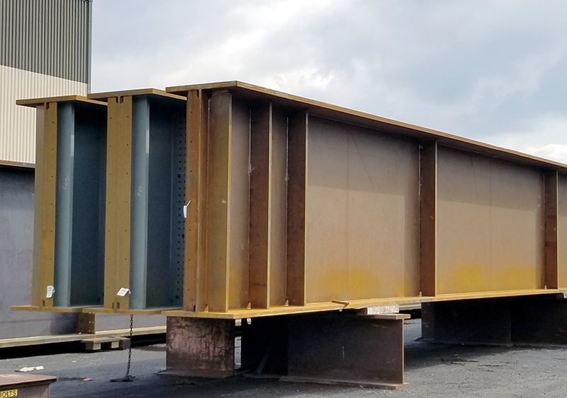
The concept for the Interchange 29 ramp bridge was to design a redundant member and facilitate shipping and handling. The triple I-girder configuration can provide load path redundancy, thereby eliminating the fracture critical designation and the special long-term inspection requirements. The details used for the fabrication of the I-girders are standard details that are easy to fabricate. The fatigue performance of these details is well studied and understood.
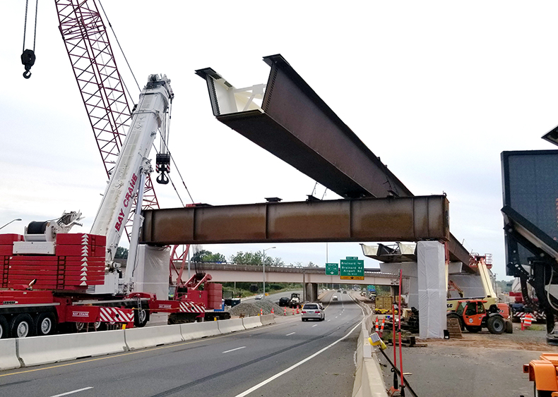
The girders can be designed for infinite fatigue life, essentially eliminating the potential for a fatigue crack to develop, let alone a fracture. The triple I-girder design also provides options to the contractor for shipping and handling. The straddle bent can be shipped and erected as one, two, or three pieces, which allows the contractor to economize on truck size and crane size, potentially eliminating an overweight permit, leading to reduced costs. This proved to be useful on the Interchange 29 ramp bridge. The contractor chose to ship the straddle bent girder in two pieces (pair and single). Once on-site, the two pieces were bolted together on the ground and erected as one piece.
The Interchange 29 ramp bridge has a stacked girder configuration, with the longitudinal girders set on top of the bent. The design team has developed similar details for an integral "framed in" design. Therefore the triple I-girder design can be adapted to virtually any steel bridge configuration.
Word has spread about this design. Texas DOT and Georgia DOT, two states that traditionally use concrete straddle bents, have both agreed that the triple I-girder bent is acceptable for widespread use. In the case of Georgia DOT, steel straddle bents were not even allowed for use. Their switch to the allowance of this design is a testament to its significance and impact on the steel bridge industry. These states and others are looking to make this design a key tool in their steel bridge toolbox.
Economy
The triple I-girder straddle bent has a surprising added benefit. It is an economical section to fabricate. During design development, the fabrication costs were considered. Initially, the team felt that the fabrication of three members might be slightly more expensive than the fabrication of a single box girder. The total flange areas of the triple I-girder would be similar to the box. The triple I-girder would have three webs, compared to two, which might increase costs. The thought was that a slight price increase might occur; however, the long-term savings in reduced fracture critical inspections would offset the initial cost.
Surprisingly, the design team was wrong. The fabrication cost for the triple I-girder turned out to be substantially less than the equivalent box girder. The fabricator has identified the fabrication savings in several ways. Box girders typically require full penetration groove welds between the webs and the flanges. Some designers specify bolted connections for this location to provide internal redundancy and obtain a fatigue Category B member. Groove welds and bolting are very expensive and time-consuming to execute in the shop. Welding a web to an I-girder flange is done every day in the shop, which makes it very cost-effective using conventional beam fabrication equipment.
Welding stiffeners and connection plates on the interior of a box girder is also costly due to confined space work that is both dangerous and time-consuming. Again, I-girder connections are easier and faster and more cost-effective to fabricate. The triple I-girder beams do require interior diaphragms with bolts; however, modern CNC machinery, which is in common use, can quickly cut and drill the plates and holes for the diaphragm. Tighter fabrication tolerances for sweep and camber must be used to provide proper fit-up; however, the cost of achieving this through minor heat cambering and straightening is easily offset by the previously noted savings. The result of these factors is that the triple I-girder straddle bent can be as much as 50% less than the cost of an equivalent box section.
The detailing of the Interchange 29 ramp bridge included leaving a small gap between the bottom flanges to allow for airflow, which eliminates the potential for a hazardous atmosphere to exist, which is a primary factor in OSHA confined space requirements. The interior of the triple I-girder with the air vent gaps would meet the OSHA definition of an OSHA "Non-permit confined space" (OSHA Standard Number 1910.146), another added benefit of this design, leading to reduced biennial inspection costs.
This innovative design provides a member with load path redundancy, less fabrication cost, reduced shipping costs, and fewer long-term costs for future biennial inspections. This is why this design is a game-changer. It represents a milestone change in the way that the industry can design and build straddle bent bridges.
Courtesy of CHA Consulting, Inc.
Project Team
-
Steel team:
-
Fabricator: High Steel Structures *AISC FULL MEMBER* *AISC CERTIFIED*
-
Detailer: abs Structural *AISC ASSOCIATE MEMBER*
-
Erector: The Hartland Building and Restoration Company*AISC FULL MEMBER*
- Bearing manufacturer: mageba USA
-
-
Engineer: CHA Consulting, Inc.
-
General contractor: O&G/BHD, JV
-
Owner: Connecticut Department of Transportation
Photo credits:
1 - CTDOT and O&G BHD
2, 4, 5 - CHA Consulting
3 - High Steel Structures
Prize Bridge Information
- Year Awarded: 2020
- Year Completed: 2021
- Location: Hartford, CT
- Award Class: Medium Span
Structure Information
- Coating System: Weathering Steel
- Span Length (ft): 140'-215'-215'-170'-140'
- Structure Length (ft): 880'
- Average Deck Width (ft): 51' 10"
- Steel Weight/Deck Area (lb/ft²): 0.0328 tsf
- Amount of Steel (tons): 1,511