AISC
In This Section
Technical Information
How much do you actually know about curved steel? Curved Steel is an art, providing endless possibilities for architectural expression. Curved steel enhances the visibility of any building project - from the largest monumental project to that building down your street. Curved Steel is a unique way to increase the design creativity of your next building project. And most importantly, Curved Steel is readily available nationally from a number of qualified AISC Associate Member Bender-Rollers.
The AISC Associate Member Bender-Rollers are committed to providing you with the answers you need. These pages should provide the information you need to get you started when thinking of using Curved Steel on your next project.
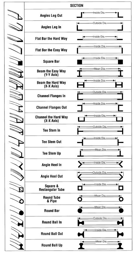
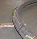
Bending Styles
The table below illustrates the available Bending Styles for structural shapes. Common terminology and essential dimensions are also indicated.
Bending Methods
There are five typical methods of bending in the industry: rolling, incremental bending, hot bending, rotary-draw bending, and induction bending. Each method has its advantages. Some methods are more commonly used in the steel construction industry, while others are more common in the automobile or manufacturing industries. The six most widely used bending processes in the industry are below, listed in order based on prevalence of use in the industry:
- Rotary-Draw/Compression Bending is where the structural member is bent by rotating it around a die. The member is clamped into a form and then is drawn through the machine until the bend is formed. This method produces tight radii and is mainly used for complicated bends in the machine and parts industry.
- Rolling (a.k.a. "Pyramid" Rolling) or Cold Bending is the typical method of curving steel for construction and is usually the most economical for rolling members with tighter radii. A steel member is placed in a machine and curved between three rolls. Cold bending may also be called "pyramid rolling" because of the three rolls' pyramid arrangement. Bending occurs when the distance between these rolls is manipulated before each successive pass.
- Point Bending or Gag Pressing is usually used for cambering and curving to very large radii. Bending is achieved by applying a minimal number of point loads with a hydraulic ram or press at selected points.
- Synchronized Incremental Cold Bending is performed by applying pressure in a highly synchronized fashion at several locations on the section. This can result in tight radii with minimal distortion.
- Hot Bending is where a structural member is heated directly and then bent. The heat source could be a direct flame or furnace. This application is used extensively in repair.
- Induction Bending uses an electric coil to heat a short section of a structural member, and then that member is drawn through a process similar to rotary-draw and cooled with water directly after. In some cases, this process can produce a smaller, tighter radius.
Specialty Bends
 |
Off-axis bends, where material is rotated out of square in cross section, require the same basic dimensional components to be specified as simple bends with one additional requirement: a cross sectional or end view of the member showing a rotation in relation to the bend plane. This rotation can be specified by degree of rotation, or triangulated dimensioning to indicate rotation. |
 |
Multiple-axis bends, where material is bent in two planes (i.e. hard way and easy way) should be specified like simple bends with dimensional components for each plane of bend addressed separately. |
 |
S-curves, where bends occur in the same plane, but in opposite directions, should be specified with the same components as simple bends. Each curve in the member needs to have dimensional components specific to that curve separately addressed. |
 |
Spirals, where bend occurs in plan view with rise in elevation view, require dimensional components from both plan and elevation views. At a minimum the following components are required: radius in plan view, degree/angle of arc or arc length in plan view, degree of pitch in elevation view, and direction of rotation (i.e. clockwise or counter clockwise as member rises in elevation). These minimum components can be represented with other dimensions, but the bender-roller must be able to arrive at these minimums. |